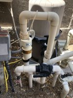
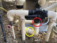
I thought I had seen a dummy cell pipe that was compatible with both Hayward and Pentair salt cells ( now I can’t find it). This led me to believe that they used the same unions, and were the same length. I just did a test fit of the Pentair union nut on an old TCELL15…and found out they are not the same…
If I have to replumb, it’s going to be a PITA, because one side of the pipe the salt cell plugs into is nothing but couplings, butted up against each other, all the way to the ground.
I’ve used split nuts before… but I’m not sure if they make one with a thread pitch that is compatible with IC40. I don’t want to mess up the threads of my nice new salt cell, just to make the split nut fit. I saw some posts on here of people using split nut on the IC40, but seems like it was not a perfect fit. I have one split nut on my TCELL, and it works just like a regular union nut. I’ve never had to mess with the screws after assembling the nut onto the pipe. It threads on and off easily when I remove the cell for cleaning.
I’m also concerned about the oring of the original TCELL union mating up with the IC40, not to mention, the IC40 seems to be a slightly different length than a TCELL (1/32” - 1/6th”, maybe).
Anyone have experience converting TCELL to IC, or know exactly which split nut will fit IC?
Thanks,Jason
Last edited:


