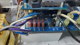
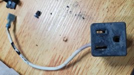
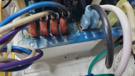
The outlet (3-Prong) for my pool motor at the bottom on my control panel shorted out and fried the black wire attached to my motherboard. I'm running a AQ-TROL-RJ system. The replacement appears easy, however, I can't find the part number to order a new outlet. Any leads on this part would be much appreciated.

Replace 3-Prong Pool Motor Outlet
- Thread starter lplatz
- Start date
You are using an out of date browser. It may not display this or other websites correctly.
You should upgrade or use an alternative browser.
You should upgrade or use an alternative browser.
- Jul 21, 2013
- 65,118
- Pool Size
- 35000
- Surface
- Plaster
- Chlorine
- Salt Water Generator
- SWG Type
- Pentair Intellichlor IC-60
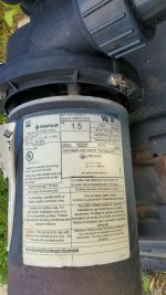
What model pump did you have plugged into that socket?
Check the solder pads to the burnt spade lugs - Hayward AquaTrol SWG - Further Reading
If you cannot find the replacement outlet you can probably wire up an external outlet placed in an electrical box directly under the Aquatrol.
Check the solder pads to the burnt spade lugs - Hayward AquaTrol SWG - Further Reading
If you cannot find the replacement outlet you can probably wire up an external outlet placed in an electrical box directly under the Aquatrol.

What model pump did you have plugged into that socket?
Check the solder pads to the burnt spade lugs - Hayward AquaTrol SWG - Further Reading
If you cannot find the replacement outlet you can probably wire up an external outlet placed in an electrical box directly under the Aquatrol.
Attachments
Thanks for the link C0d3Sp4c3. The challenge in finding these items if pursuing cold w/o a product number is what is the general item description. I appreciate your help/lead. This is a great start.or Google search for "panel mount ac receptacle" and compare the dimensions.
How about this one?
- Jul 21, 2013
- 65,118
- Pool Size
- 35000
- Surface
- Plaster
- Chlorine
- Salt Water Generator
- SWG Type
- Pentair Intellichlor IC-60
That pump is too powerful at 1.5HP and pulling 15 amps for the Aquatrol circuit. Maximum load on a 15A circuit should be 12A. You will continue to burn out wires and components using that pump on that outlet..
That's good to know (as I repair and move forward). The is a relatively new motor having just replaced it w/in the last two years. I inherited this pool when we purchased our home and the motor previously installed was also a 1.5HP. Can you point me in the right direction w/in the TFP forums on finding a replacement motor, properly sized, that will fit my system?That pump is too powerful at 1.5HP and pulling 15 amps for the Aquatrol circuit. Maximum load on a 15A circuit should be 12A. You will continue to burn out wires and components using that pump on that outlet..
- Jul 21, 2013
- 65,118
- Pool Size
- 35000
- Surface
- Plaster
- Chlorine
- Salt Water Generator
- SWG Type
- Pentair Intellichlor IC-60
Give us some clues as to what model pump that motor is connected to.
You probably want a 3/4HP or 1HP motor and will need to downsize the impeller for the reduced motor HP.
You probably want a 3/4HP or 1HP motor and will need to downsize the impeller for the reduced motor HP.
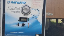
I can't seem to catch a break. I just finished repairing my panel mount outlet plug to my pool pump motor. Plugged my control panel in and now all lights are illuminated solid, not blinking. The display is showing only 1/2 the screen. Any ideas or leads?
Attachments
C0d3Sp4c3
Well-known member
- Dec 10, 2018
- 330
- Pool Size
- 20000
- Surface
- Plaster
- Chlorine
- Salt Water Generator
- SWG Type
- Hayward Aqua Rite (T-15)
Reseat the display bd and make sure the contact pins are sitting properly in place.
- Jul 21, 2013
- 65,118
- Pool Size
- 35000
- Surface
- Plaster
- Chlorine
- Salt Water Generator
- SWG Type
- Pentair Intellichlor IC-60
I just finished repairing my panel mount outlet plug to my pool pump motor.
Where did you find the outlet? Care to share details?
Amazon of courseWhere did you find the outlet? Care to share details?
 . Search: "15A 125V AC Panel Mount Outlet Industrial Plug Female Connectors Adapter With 14AWG Connection line,3 Pins US Power Socket Plug Panel". I had to purchase a 2 pack, but I received it next day, so I don't mind having a backup. It was a perfect fit. To complete the install, I had to purchase some 16-14 AWG female spade connectors (.250) to crimp on the ends for black and white wires and a ring terminal connector for the ground wire.
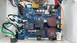
I completed the reseat. I then replaced the female spade connectors for the gray, violet, white & blue lines coming into the board next to the black & white outlet wires. They had incurred some heat damage, so I decided while I had it torn apart, I'd install new connectors. After finishing that, I tested system again. This time, it cycled through the "no flow" light. After that light went off, I was expecting my Generating light to come on. I usually hear a click w/in 5 to 10 seconds and the Generating light comes on... it did not.Reseat the display bd and make sure the contact pins are sitting properly in place.
 I tested the Thermistor for continuity and it passed. I'm beginning to think it's either my display board or motherboard. Hoping someone has some fresh ideas.
- Jul 21, 2013
- 65,118
- Pool Size
- 35000
- Surface
- Plaster
- Chlorine
- Salt Water Generator
- SWG Type
- Pentair Intellichlor IC-60
Check the solder points on the K1 and K2 relays.
The K1 and K2 relays are the click you hear and control the power to the cell. If the K1 or K2 relay is not working then the cell will not get power to generate.
The K1 and K2 relays are the click you hear and control the power to the cell. If the K1 or K2 relay is not working then the cell will not get power to generate.
I ran a continuity test across all solder contact on the bottom of the board. Although I don't know the internal relays, my initial thought is both K1 and K2 are good.Check the solder points on the K1 and K2 relays.
The K1 and K2 relays are the click you hear and control the power to the cell. If the K1 or K2 relay is not working then the cell will not get power to generate.
- Jul 21, 2013
- 65,118
- Pool Size
- 35000
- Surface
- Plaster
- Chlorine
- Salt Water Generator
- SWG Type
- Pentair Intellichlor IC-60
Could be a bad thermistor.
From Hayward Aquarite SWG - Further Reading
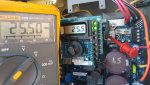
If the thermistor is good, the voltage reading on the display matches the measured voltage from the thermistor lead farthest from the Red terminal on the board as shown. Make sure the Blk test lead is on the Negative side (not Ground) which is the black terminal or to the R15 (.015 Ω) link as shown in the pic.
The thermistor on the SWG is a Negative Temp Coefficient (NTC) thermistor, so resistance will decrease as temp increases. The rating for the thermistor is 2 ohms at room temp (low 70’s F), which is about the reading you should get on a multimeter, give or take a little depending on temp. If it’s wayyy off, it’s bad. If it’s close, proceed.
The next test is, while holding the two leads of the multimeter on the legs of the thermistor, apply a heat source (hair dryer, heat gun, etc.) for a few moments. The resistance reading should begin to drop as the heat source is applied. If not, it’s bad.
From Hayward Aquarite SWG - Further Reading
If the thermistor is good, the voltage reading on the display matches the measured voltage from the thermistor lead farthest from the Red terminal on the board as shown. Make sure the Blk test lead is on the Negative side (not Ground) which is the black terminal or to the R15 (.015 Ω) link as shown in the pic.
The thermistor on the SWG is a Negative Temp Coefficient (NTC) thermistor, so resistance will decrease as temp increases. The rating for the thermistor is 2 ohms at room temp (low 70’s F), which is about the reading you should get on a multimeter, give or take a little depending on temp. If it’s wayyy off, it’s bad. If it’s close, proceed.
The next test is, while holding the two leads of the multimeter on the legs of the thermistor, apply a heat source (hair dryer, heat gun, etc.) for a few moments. The resistance reading should begin to drop as the heat source is applied. If not, it’s bad.
C0d3Sp4c3
Well-known member
- Dec 10, 2018
- 330
- Pool Size
- 20000
- Surface
- Plaster
- Chlorine
- Salt Water Generator
- SWG Type
- Hayward Aqua Rite (T-15)
Is your pump running? Can you post the diagnostic readings?This time, it cycled through the "no flow" light. After that light went off, I was expecting my Generating light to come on. I usually hear a click w/in 5 to 10 seconds and the Generating light comes on... it did not.
Can't remember if the 'No Flow' blinks on a RJ during the initial start-up. But the 'Click' sound you are referring to will happen exactly 10 seconds after the 'Generating' LED has turned on.
Let's hope that this is not another AL-5 issue!
Darin
Well-known member
- May 29, 2015
- 556
- Pool Size
- 35000
- Surface
- Vinyl
- Chlorine
- Salt Water Generator
- SWG Type
- CircuPool RJ-60 Plus
Unfortunately, no diagnostic readings are available via the display. Are there other diagnostic readings I can get via a multi-meter? It is my experience with my panel that as soon as the "no flow" goes out, the "generation" light comes on and the familiar click occurs after 10 seconds. That's my confirmation that the T-Cell is generating. What is the "AL-5 issue"?Is your pump running? Can you post the diagnostic readings?
Can't remember if the 'No Flow' blinks on a RJ during the initial start-up. But the 'Click' sound you are referring to will happen exactly 10 seconds after the 'Generating' LED has turned on.
Let's hope that this is not another AL-5 issue!
C0d3Sp4c3
Well-known member
- Dec 10, 2018
- 330
- Pool Size
- 20000
- Surface
- Plaster
- Chlorine
- Salt Water Generator
- SWG Type
- Hayward Aqua Rite (T-15)
Product ID getting stuck in AL-5 instead of the correct AL-7 in the diagnostics. Tell tale sign that EEPROM data is corrupted presumably caused by voltage spike or lightning. But you need to get the display bd going to confirm. Maybe you have a bad disp bd.Unfortunately, no diagnostic readings are available via the display. Are there other diagnostic readings I can get via a multi-meter? It is my experience with my panel that as soon as the "no flow" goes out, the "generation" light comes on and the familiar click occurs after 10 seconds. That's my confirmation that the T-Cell is generating. What is the "AL-5 issue"?
Thread Status
Hello , This thread has been inactive for over 60 days. New postings here are unlikely to be seen or responded to by other members. For better visibility, consider Starting A New Thread.