Removing Pump Timer & Switch

KDpoolguy

0
Bronze Supporter
Mar 5, 2017
603
Palm Desert, CA
Pool Size
17000
Surface
Plaster
Chlorine
Salt Water Generator
SWG Type
Hayward Aqua Rite (T-9)
Been 3 years since we have had the Variable Speed pump and the old Intermatic mechanical timer for the original 1-speed pump is still there spinning, with the on-off pins removed. The pad sits behind our master bedroom and sometimes I can hear the timer spinning. That’s motivation for removal in itself.

The electrical setup has this mechanical timer and a concurrent on-off Switch (looks like a 120v standard light switch) in same box with the pool light and spa jet switch is-closer to pool. It was convenient to turn on pump for manual vacuuming and such.

It’s a neat setup for a single-speed pump where the pump-on-off Switch and timer work independently through a magnetic mechanism (not sure the term for it). I now have a super dumb Do Not Touch label on the pump Switch, as if someone touches it, it can turn the power to VS pump off, erasing memory. It may confuse the future renter or owner if I sell or rent my house. Now that we’re in a world of VS pumps, I’m sure there are many of us with this setup that’s no longer needed. My original feeling was to use this timer and switch to hook it up to my future SWG, but now that’s probably not gonna happen.

I don’t think it’s too crazy for a DIY job to remove timer as I’m sure it’s just a matter of removal and maybe replacing with a outlet box that houses the wire nuts to bypass it. What have you done?
 
Removing the timer or even just cutting the power wires to the timer motor is easy enough.
I would not remove the pump switch, code in most areas requires a means to disconnect power to a piece of equipment within sight of the equipment for safety.
 
A CB in a panel within sight of the pump will satisfy code and allow the switch to be removed.

I agree with Jim R. that removing the power to the clock motor solves the immediate problem of the noise. But then you have the issue of it being a rental house. The timer not running can confuse renters and even if the switch is labeled emergency cutoff renters will turn it off.

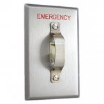
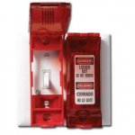
There are various wall switch guards such as the one below that can be installed to emphasize that the switch is for emergency use only.

If you want to redo the wiring then post some pics of your pump area, CB panel, timer and switch so we can see your situation. There are many ways this could have been installed.

toggle_switch_locking_guard_strap__87249.1352298831.1280.1280.jpg

123267.jpg
 
Removing Pump Timer & Switch

There are various wall switch guards such as the one below that can be installed to emphasize that the switch is for emergency use only.

If you want to redo the wiring then post some pics of your pump area, CB panel, timer and switch so we can see your situation. There are many ways this could have been installed.
d25a29265d5ed9128518de32a528f769.jpeg


I removed the insulator cover on the timer to investigate the wiring and I’ll have to decipher this.
The switches were replaced with large and smaller rocker Decora-style switches. I can rearrange the switches to get a toggle guard I presume. The CB are easily accessible as a fireman’s Switch as shown.
I can post closer images of the wiring if that helps. I’d like to just keep the timer box, but bypass it with some wire nuts. The center box has the magnetic switch that allows the switch to countermand the power direction from the timer.

I won’t need a timer for an SWG like the Circupool RJ16, will I? It has a timer in it, correct, If I’m gonna tackle this, I’m inclined to install an SWG soon and prep the area to wire one in. (Edit: read instruction manual and it has a flow switch, so no timer should be necessary.)
 
You’ll want a timer for the SWG. The flow switch is a safety device and should not be relied on for daily operation.

OP should check if his pump has a relay to power the SWG when on.

The existing timer is not useful for the SWG the way it is connected.
 
OP should check if his pump has a relay to power the SWG when on.

My pump info is in signature, but I’ve yet to check on it myself. I you know off hand?

I’d like to disconnect the timer tomorrow, and I’m doing some other maintenance on the pad also. Help is appreciated.
The magnetic relay is a bit of a mystery in its brilliance.
 
My pump info is in signature, but I’ve yet to check on it myself. I you know off hand?

Does not look like your pump has a relay to power a SWG.

I’d like to disconnect the timer tomorrow, and I’m doing some other maintenance on the pad also. Help is appreciated.
The magnetic relay is a bit of a mystery in its brilliance.

You need to post pics of the exposed wiring to show us how it is wired.
 

Enjoying this content?

Support TFP with a donation.

Give Support
aacfde59e4c253a623587a0685b98978.jpg

Here’s the timer. I’m perplexed at the 220v setup power to 1/3 and 2/4?

What model timer is that? Should be on the inside of the door?

I think this is the wiring setup for it. From https://www.intermatic.com/-/media/inriver/10053-9051.ashx/T104-Instructions-EN

2018-09-24_1502.png

1 & 3 are the two 220V line wires from the CB. 2 & 4 go to the pump or switch. It looks like the timer is powering two things from the two wires on 2 & 4.

If you wire nutted the three wires on 1 & 2 and on 3 & 4 you would take the timer out of the circuit.

What we don't have here is how the switch is wired into the pump circuit.
 
3b352e0a2e5b4c08f7b0ebd8fa886ebd.jpg

With relay

You have to trace where the two wires on the timer screw 2 and the two wires on 4 connect to. Impossible to follow it on the pic.

Is there any label for the manufacturer and model number of that relay box?
 
Removing Pump Timer & Switch

What model timer is that? Should be on the inside of the door?

What we don't have here is how the switch is wired into the pump circuit.

Timer model: T104R

I’m revisiting all wiring. I have one CB off that powers Spa Jets & Lights) Jet pump is powered by 2 20 amp breakers, one that’s connected to GFI).

Just discovered that switch is inoperable when this 3rd CB is off, perhaps all the switches to that light switch box must run thru a GFI? If GFI is off, this pump switch doesn’t work-so little use as a true cut-off fireman switch. Power to timer is the dominant power source.

On Timer-To remove power from timer clock. Can I just remove jumpers to 1 or 3? Just want clock motor to stop turning, but still have 100% always on power to pump.

3rd CB is off as I’m working on pool/spa lights -waiting until temps go below 110 ;). It’s hard to work out here longer than an hour.
 
You have to trace where the two wires on the timer screw 2 and the two wires on 4 connect to. Impossible to follow it on the pic.

Is there any label for the manufacturer and model number of that relay box?

No manufacturer for the relay box, custom job it appears. 3 different relays-they are all showing the switchable portions are linked to the main pool pump. All relays are in (magnetized) position pushed toward me, so I’m assuming it’s a setup to allow pump to turn ON when Timer is OFF. It’s all really useless with a VS pump, but let’s leave it be ;)

Traced 2 Pair of Wires coming from 2/4:
1st pair: They go to power the pump, so they are traced into conduit going to pump.
2nd pair: They go to switchable (bottom area) of the relay in upper right of box. There is power going to this area on the relay.
 
Removing Pump Timer & Switch

Take the red wire from 1 and put under 2
Take the red wire from 3 and put under 4

This will bypass timer and remove power from timer motor.

If I just remove the white clock power wires from 1 or 3 or both 1&3, will that just stop the motor and still allow me to use the timer’s manual On/Off Switch?

That would be my preference in case someone else goes to turn off and finds it’s been completely bypassed.

EDIT: I disconnected clock timer power from #1 and now clock timer stops working, but manual ON/OFF still works.
Anyone have any objections to this?

I’ll put some electrical tape/heat shrink to cover metal part of white power wire (to #1- clock) and a note on how to reconnect.
 
Re: Removing Pump Timer & Switch

If I just remove the white clock power wires from 1 or 3 or both 1&3, will that just stop the motor and still allow me to use the timer’s manual On/Off Switch?

Yes

EDIT: I disconnected clock timer power from #1 and now clock timer stops working, but manual ON/OFF still works.
Anyone have any objections to this?

I’ll put some electrical tape/heat shrink to cover metal part of white power wire (to #1- clock) and a note on how to reconnect.

That is fine.

- - - Updated - - -

No manufacturer for the relay box, custom job it appears. 3 different relays-they are all showing the switchable portions are linked to the main pool pump. All relays are in (magnetized) position pushed toward me, so I’m assuming it’s a setup to allow pump to turn ON when Timer is OFF. It’s all really useless with a VS pump, but let’s leave it be ;)

Traced 2 Pair of Wires coming from 2/4:
1st pair: They go to power the pump, so they are traced into conduit going to pump.
2nd pair: They go to switchable (bottom area) of the relay in upper right of box. There is power going to this area on the relay.

So the timer is powering both the pump and the circuits that run through the relay box.

Have you figured out what each relay is wired to?

There any reason you would want the pump to always be powered and the other circuits through the relay on the timer?
 
Removing Pump Timer & Switch

So the timer is powering both the pump and the circuits that run through the relay box.

Yes, so when timer manual on/off switch is moved to OFF, the relay (that’s powered off Load from timer 2/4) disengages while also removing power from pump.

Have you figured out what each relay is wired to?

Just tied into pool pump, but It’s hard to figure out all the wires, as some are just powered off the relays, without any reliance on their on/off status (i.e. heater seems to get power off one of them). The 2 top relays are powered off 2 different 20 amp CB’s, so both must be on to run main pump.

There any reason you would want the pump to always be powered and the other circuits through the relay on the timer?

Not really, but short of opening up all junction boxes to see where wires go to places other than pump, and as long as relays are working, I’m good with just leave them be. Is that what you’re asking?

Thank you for the swift help. Gonna take a break for the day. The GFI (Leviton Blankface 20amp GFCI) I replaced months ago still isn’t working (argh).

Why would the light switch (pump switch) only work on the GFI curcuit? As soon as I discovered this, I wanted to keep timer manual switch on and active since it has master control of the pump if the GFI circuit is off or GFI itself is tripped.
 

Enjoying this content?

Support TFP with a donation.

Give Support
Thread Status
Hello , This thread has been inactive for over 60 days. New postings here are unlikely to be seen or responded to by other members. For better visibility, consider Starting A New Thread.