Question connecting Intelliconnect to ichlor and the intelliph wall panel at the same time.

Jun 29, 2010
100
TT
Seeking practical wisdom pls...

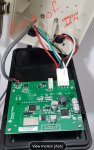
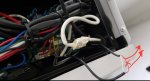
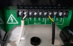
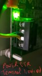
I am attempting to connect ichlo30 to the right side pair of RS485 terminals. I figured if I Daisy chained a wire, to the power center which had a yellow+ green terminal block inside it should work but the Link2o says comm error.
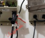
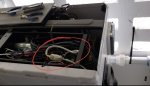
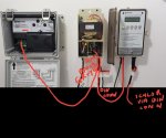
As you can see in the photo, the power center is connected to the intelliph control unit which is connected to the ichlor.

The close up photo shows the green and yellow stranded wire going from the load ctr to the Intelliconnect.

I would like not to eliminate the intelliph units ability to control the ichlor.
 

Attachments

  • Screenshot_20191121-115045_Gallery.jpg
    Screenshot_20191121-115045_Gallery.jpg
    134.4 KB · Views: 130
  • Screenshot_20191121-115210_Gallery.jpg
    Screenshot_20191121-115210_Gallery.jpg
    157.4 KB · Views: 104
Are you sure the wires are making good contact and not hanging up on the insulation?

Did you reboot the Intelliconnect, powering it off and on, aftre connecting the RS-485 wire?

Show us a pic of the RS-485 connection in the IntelliConnect.
 
Thanks aj22...

Well here's an update. Checked out all of your suggestions and went a bit further to test the male portion of the DIN connector on the power center's base. Turns out the wire block inside, for the green and white wires FAILS CONTINUITY to the said connector. Well that explains that. Now the usage of that terminal block is not documented in the power center manual so I can't really call foul.

So went on to splice my Intelliconnect rs485 wire directly to the green and white wires inside the power center..... Mind you it's green and white inside there, not green and yellow. Well .... Now reporting partial success! See attachment
 

Attachments

  • Screenshot_20191121-151125_LinkO.jpg
    Screenshot_20191121-151125_LinkO.jpg
    95.7 KB · Views: 57
Hi aj, am definitely missing something here.

To answer your question, it correctly shows 75, and responds to manipulation on the intelliph up or down.

I downgraded my success to 0. The readings for the salt and temp are in fact static I noted subsequently. In case I had a polarity issue i swapped the rs485 wires and that messes things up to the point where the intelliph thinks the pump is off and refuses to dose acid, and the temp reads 100. So I definitely have a mis wiring here since the Intelliconnect controls the vsf pump fine.

I find the installation instructions paltry tho. For example, let's say I in fact wanted to connect the ichlor directly, the cable from it is a 4 wire round plug. How on earth is that to connect to the Intelliconnect without cutting that cable? In case I am missing items from the box, there were no cables that came with the unit.

Thanks for your thoughts.
 
I now see on Page 4 of the Intelliconnect Manual says:

When an IntelliChlor or iChlor SCG is wired to IntelliConnect via RS-485, a power connection to the load side of the pump relay is not required. Digital commands sent from the IntelliConnect to the SCG will not allow chlorine production when there is low power or no power onthe filter pump relay or when the IntelliFlo is not running.

Only wire the RS-485 cable's yellow and green conductors to the IntelliConnect's RS-485 terminal.


Did you try just connecting the iChlor to the Power Center and the yellow/green wires to the IntelliConnect and see that you have communication and control of the iChlor?

Once you get the iChlor running alone then put the IntellipH in series by just moving the iChlor cell cable into the IntellipH Controller and the IntellipH Controller into the Power Center.
 
op,

I admit I don't know much about your system, but I think you are peeing into the wind... :mrgreen: The whole system is designed for the the ipH to control the SWCG, so I can't see how hot wiring the RS-485 is going to get you anywhere.. The DC power to run the ipH comes from the SWCG's power supply and is then routed from the ipH to the SWCG... I would think the programming to control the SWCG, in this configuration, is inside the ipH and not your IntelliConnect.

But, as I said, I am not up on your system, so I could be wrong, but on the surface I doubt what you want to do will work.

Please let us know if you get it working as it might help other with the same problem. It won't my feelings as I've been wrong about a hundred times... just today.. :)

Thanks,

Jim R.
 
Yes Jim, I'm not sure it is possible either. The iPh I guess doesn't factor in to prominently in most set ups.

IPh aside though, still don't see how an ichlor goes to an iconnect without cutting wires.

And the link app? Not inspiring confidence because I disconnected the 'test' rs485 wire from the second person and it still shows Connected..... Of course 3250ppm and a warm 98dF.
 
I now see on Page 4 of the Intelliconnect Manual says:

When an IntelliChlor or iChlor SCG is wired to IntelliConnect via RS-485, a power connection to the load side of the pump relay is not required. Digital commands sent from the IntelliConnect to the SCG will not allow chlorine production when there is low power or no power onthe filter pump relay or when the IntelliFlo is not running.

Only wire the RS-485 cable's yellow and green conductors to the IntelliConnect's RS-485 terminal.


Did you try just connecting the iChlor to the Power Center and the yellow/green wires to the IntelliConnect and see that you have communication and control of the iChlor?

Once you get the iChlor running alone then put the IntellipH in series by just moving the iChlor cell cable into the IntellipH Controller and the IntellipH Controller into the Power Center.

Will try this in the morning and revert AJ22
 

Enjoying this content?

Support TFP with a donation.

Give Support
op,

Forgetting about the ipH for a minute, the IChlor plugs into the bottom of the SWCG's power center.. Then you use a two wire cable and connect one end to the yellow and green pins on the RS-485 IntelliConnect connector and the other end to the yellow and green pins on the power center's RS-485 connector. In theory, the power center should provide the DC voltage to run the cell and the IntelliConnect should be able to control the cell and read the salt level... Of course the Power Center must be connected to 120 or 240 Volts from a breaker...

I would make sure that works first before doing anything else..

If you have connected it wrong, you can easily blow up the RS-485 bus chips..

Thanks,

Jim R.
 
Well Jim I haven't fried it.... yet it seems... But thanks for the heads up.

Ok guys so tested your suggestion and eliminated the IPh for now and ta da ... It works. Shows 3050ppm, the temp is about 10 degrees off but this time I can adjust percentages to the ichlor and boost from the app.

Problem now is that I can't dose.

Looking into the IPh you can see it seems to just tap off the green and white wires from one circular connector as it passes to the second circular connector at base.

So at this point, it seem so either to have swg be automation or dosing but not both.
 

Attachments

  • Screenshot_20191122-073244_Gallery.jpg
    Screenshot_20191122-073244_Gallery.jpg
    139.5 KB · Views: 43
  • Screenshot_20191122-073211_Gallery.jpg
    Screenshot_20191122-073211_Gallery.jpg
    271.6 KB · Views: 40
Moving on though, do any of you folks know if I can use one of the relays to interrupt at will the flow switch off my Hayward heat pump, much like Jimrahbe's post outlined with the dry contact relay of an intellitouch?

I hooked up the supply of the heat pump to be relay 2 but it seems like too an abrupt way to stop the heat pump.

I also have the 12v and network terminals of the OPs heat pump but it is unknown if he got it to work.
 
Ok this is a wrap.
I got the intelliph to coexist with the Intelliconnect.... The original approach worked ... Just that I realised I had to wait a bit longer for it to get a signal from the Intelliconnect. Now the iPh prompts you to adjust the swcg 'via automation' but will dose as normal. It sure would be nice for a app upgr to be able to adjust the dosage.

The relays in fact work well in controlling the flow detector of the heat pump as Jim had proposed. See photos.

Next step is to get a temp probe so I can actually set target temps.

Thanks again to all.
 

Attachments

  • Screenshot_20191122-171921_Gallery.jpg
    Screenshot_20191122-171921_Gallery.jpg
    90.1 KB · Views: 53
  • Screenshot_20191122-171901_Gallery.jpg
    Screenshot_20191122-171901_Gallery.jpg
    95.9 KB · Views: 55
  • SmartSelect_20191122-171824_Gallery.jpg
    SmartSelect_20191122-171824_Gallery.jpg
    71.6 KB · Views: 59
Thread Status
Hello , This thread has been inactive for over 60 days. New postings here are unlikely to be seen or responded to by other members. For better visibility, consider Starting A New Thread.