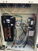
Just following up. Went ahead and bought a new pump and replaced the existing breaker with a GFCI. Also moved the salt cell wiring to the relay. Does this look correct? I also bought a square D surge protector. I think it connects to its own 240v 20amp breaker. Does this just go in any available space?Chad,
Do you have a salt cell? If so the SWCG transformer is not wired correctly either .. It should be wired through the pump/filter relay, not directly to a circuit breaker..
Thanks,
Jim R.

Pump Won’t Power On - No Display
- Thread starter ChadS44
- Start date
You are using an out of date browser. It may not display this or other websites correctly.
You should upgrade or use an alternative browser.
You should upgrade or use an alternative browser.
- Jul 21, 2013
- 65,762
- Pool Size
- 35000
- Surface
- Plaster
- Chlorine
- Salt Water Generator
- SWG Type
- Pentair Intellichlor IC-60
You do not have any power feeding the line side screws 1 & 3 of the relay you have the SWG transformer connected to.
You should not have two wires connected to one terminal on a CB which you did on the pump CB.
You should wire the 20 amp GFCI relay to Line screws 1 & 3 on the first relay.
You can put two wires under one screw on the relay screws. So you connect the pump to the line side screws of the relay.
What is the other wire connected to the 20Amp CB for?
If you need to connect more loads then you create a pig tail wire to pick up the circuit and wirenut together the wires for the devices,
You should place the 20amp CB for the surge suppressor in the position closest to the power feeds into the panel which are at the bottom.
Hey everyone, someone pointed out that my salt water generator was wired directly to the circuit breaker. I disconnected and moved the wires to the filter/pump relay. Does this look correct? Each wire that Goes to the salt transformer is connected to the load lug on the relay. Do I need something coming from a breaker that goes to the line sides? Thank you.
Attachments

- Jul 21, 2013
- 65,762
- Pool Size
- 35000
- Surface
- Plaster
- Chlorine
- Salt Water Generator
- SWG Type
- Pentair Intellichlor IC-60
Do I need something coming from a breaker that goes to the line sides? Thank you.
Yes, see my post in your other thread.
On that dual pole GFCI breaker I’ve got the 240v vsf pump (the manual says to wire it directly to the breaker) and I’ve got the primary control transformer on that same breaker.You do not have any power feeding the line side screws 1 & 3 of the relay you have the SWG transformer connected to.
You should not have two wires connected to one terminal on a CB which you did on the pump CB.
You should wire the 20 amp GFCI relay to Line screws 1 & 3 on the first relay.
You can put two wires under one screw on the relay screws. So you connect the pump to the line side screws of the relay.
What is the other wire connected to the 20Amp CB for?
If you need to connect more loads then you create a pig tail wire to pick up the circuit and wirenut together the wires for the devices,
You should place the 20amp CB for the surge suppressor in the position closest to the power feeds into the panel which are at the bottom.
- Jul 21, 2013
- 65,762
- Pool Size
- 35000
- Surface
- Plaster
- Chlorine
- Salt Water Generator
- SWG Type
- Pentair Intellichlor IC-60
On that dual pole GFCI breaker I’ve got the 240v vsf pump (the manual says to wire it directly to the breaker)
You read that too literally. You can wire the VSF pump direct to the breaker through the line side screws of the relay.
and I’ve got the primary control transformer on that same breaker.
That will cause your entire system to go dark if the pump trips the breaker.
You have an unused 120V breaker. What was your intention with that?
You should power the panel from a separate 120V breaker.

Ok. Makes sense. So the pump can go to the line side of the relay and then run from the relay to the breaker? There is actually a wire going into the extra breaker. It goes to a GFCI receptacle on my post. So right now, my primary control transformer goes to the 240v breaker. Will I need a separate dual pole breaker for this?You read that too literally. You can wire the VSF pump direct to the breaker through the line side screws of the relay.
That will cause your entire system to go dark if the pump trips the breaker.
You have an unused 120V breaker. What was your intention with that?
You should power the panel from a separate 120V breaker.
- Jul 21, 2013
- 65,762
- Pool Size
- 35000
- Surface
- Plaster
- Chlorine
- Salt Water Generator
- SWG Type
- Pentair Intellichlor IC-60
The panel can run off 120V. The manual describes how to wire it for 120V.
You can then connect it to the line side of the outlet. Or pigtail off the circuit breaker and wire nut together the wires to the outlet and transformer.
You can then connect it to the line side of the outlet. Or pigtail off the circuit breaker and wire nut together the wires to the outlet and transformer.
Last edited:
Thread Status
Hello , This thread has been inactive for over 60 days. New postings here are unlikely to be seen or responded to by other members. For better visibility, consider Starting A New Thread.