Pump inlet minimum straight length.
- Thread starter czb182
- Start date
You are using an out of date browser. It may not display this or other websites correctly.
You should upgrade or use an alternative browser.
You should upgrade or use an alternative browser.
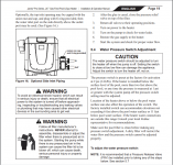
The pressure switch is preset at the factory for activation at 2 psi (14 kPa).
The pressure switch is not going to be set to 7 psi.
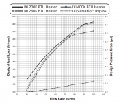
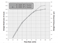
As you can see from the head loss charts above, the heater does not create 7 psi until the water flow is 87 gpm.
7 psi has to be a typo.
Typical heater pressure switches are set to 2 or 3 psi.
Assuming that the heater is a JXi 400, the heater needs 40 gpm, which will create about 4.6 feet of head or about 2 psi.
Last edited:
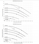
I think that one of the below pump performance curves should go to your pump.
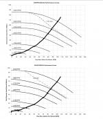
Once you are operational, you can plot your system curve on the pump curve to find the operating points.
The operating points are where the system curve intersects with a pump curve.
You can measure the TDH (Total Dynamic Head) or the flow in gpm and then put the dots and draw the curves as shown in a hypothetical example below.
If we assume 12 feet for the suction at 80 gpm, the pressure side should be the filter pressure x 2.31.
I would estimate the suction head loss to be about 40% of the return head loss.
If the return head loss is 30 feet, we can estimate the suction head loss to be 12 feet.
For example, if the speed is 2,750 rpm and the filter pressure is 13 psi, we can estimate the return head loss as 13 x 2.31 = 30 feet and the TDH would be 30 + 12 = 42 feet.
So, we put a dot at 42 feet on the 2,750 curve, which is 80 gpm.
Or, you can measure the flow and then put the dot at 80 gpm to find the head loss.
You can install a vacuum gauge to get the actual suction head loss if you want to be more accurate than estimating at 40% of the return head loss.
You can install a flow meter to see what the flow is to make sure that the flow to the heater is correct before you set the pressure switch or install a flow switch.
I would install a flow switch for the heater and a flow meter on the system and maybe add a vacuum gauge to the suction.
Notice that the pump will drop the rpm at 115 volts if necessary to keep the amperage below the maximum specified in the manual.
So, be sure to use 230 volts and not 115 volts.
The maximum is 16 amps at 115 volts so that the pump won't exceed 80% on a 20 amp breaker.


Last edited:
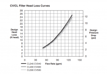
If you want to know the individual components of the head curve, you can look them up on the charts.
For example, at 80 gpm, the filter will contribute about 10 feet of head loss, the heater will contribute about 15 feet of head loss, and 100 feet of 2” pipe will contribute about 10 feet of head loss.
The total components on the return will equal to 5 feet more than the filter pressure will indicate because you have to subtract the 5 foot drop back to the pool.
10 + 15 + 10 -5 = 30 feet.
Do you feel like you wanted a sip of water but got the firehose? LOL.

Im still trying to understand mechanics of pool pressure switch. there needs to be enough pressure pushing against it to close the circuit. the pressure differential is between the inlet of the heater(right after filter) and the pool/spa return? The heater itself creates quite a bit of back pressure as you mentioned. then it has to go through check values, 3 way values, piping. it must be return dynamic head right(minus filter and anything before it I suppose)? all the restrictions added post filter exit , then minus the elevation (~5 feet)? so for return this would be 20 feet at 80 gpm roughly, which would easy close switch. so a higher elevated pad closing switch is helped by more restrictive return side? This can't be right thought, because manual doesnt make any mention of head loss on return, only the elevation(same as static head right?) Thinking as i'm typing. IF this is true then i only need 7 feet of head loss to close 2 psi switch, so if i have at least 7 feet head loss post filter. the heater itself would generate this at 46 gpm, taking into account everything piping related it should be much lower, maybe even at minimum.
i have a feeling everything i just wrote above it wrong, lol.
i have a feeling everything i just wrote above it wrong, lol.
other thing im trying to understanding is relationship between suction and return side head loss. I thought I had ready that suction side head loss should always be much lower than return to avoid caviation, but I'm thinking this is not true, it only matters that suction side head loss is low(no more than 12 as you said), irrespective of return side head loss. For instance, if we had the 3 way valve on pump outlet, going to waste, it would be very little return side head loss, but that would not cause any issues. only if suction side is high would there be issues.
as an aside, i suppose you could have negative head loss? like the the outlet of pump was connected to pipe going straight down 5 feet, then you would have close to -5 head loss on return?
as an aside, i suppose you could have negative head loss? like the the outlet of pump was connected to pipe going straight down 5 feet, then you would have close to -5 head loss on return?
If the pressure switch is before the heater on the inlet to the heater, then the heater head loss counts toward the total pressure required to close the switch.
However, if the pressure switch is after the heater on the outlet of the heater, then the heater head loss won't count toward the total pressure required to close the pressure switch.
Only the head loss created after the heater would count toward the total pressure required to close the switch.
Once you get everything running and you can verify that the flow is good, see if the pressure switch is closed and you can adjust it as needed.
What is the model number for the heater?
The only thing that creates cavitation is the suction side vacuum pressure (aka head loss).
The return side makes no difference.
However, if you have a high head pump and low head loss on the return side, the head loss on the suction side will probably be too much.
So, there is a relationship or rule of thumb that makes sense to keep the suction head loss lower than the pressure side head loss.
Correct. The rule mostly came about in the past when most pumps were single speed high head pumps that were way too big and most plumbing was way too small.For instance, if we had the 3 way valve on pump outlet, going to waste, it would be very little return side head loss, but that would not cause any issues. only if suction side is high would there be issues.
With a variable speed pump and properly sized suction plumbing, you should never have cavitation if you know what you're doing.
If a pump is below the surface of the pool far enough, you can have a situation where the pressure in the suction is never a vacuum and is always positive.as an aside, i suppose you could have negative head loss? like the the outlet of pump was connected to pipe going straight down 5 feet, then you would have close to -5 head loss on return?
For example, if the pump is 10 feet below the surface of the pool and the suction head loss is 8 feet, the pressure is a positive 2 feet.
So, you gain 10 feet on the suction side and lose 10 feet to the return side.
Ok. Looks like the heater head loss will apply.
At the required 40 gpm, it should provide about 4.6 feet of head loss or about 2 psi.
If the pressure switch is set to 2 psi and the static drop is 2 psi that makes a total of 4 psi plus 1 for margin equals 5 psi.
5 - 2 for the heater means that everything after the heater has to provide 3 psi or 7 feet of head.
If the plumbing is 100 feet of 2" pvc at 40 gpm it will create about 4 feet of head loss, which leaves about 3 feet.
You will probably be able to adjust the pressure switch enough to make it work.
this has been very enlightening. thank you for your time and knowledge. i guess we kind of drifted away from original question, which im still a little curious about. How did this recommendation of 4-6 times diameter of pipe come to be? i can't see how it makes a difference unless pipe is leading straight to impleller, which its not, it flows through basket. its enforced in pool code and manufacturers recommended it, so it must have value but i can't see how
Just to provide laminar flow.
With the basket, it really doesn't matter.
If the there was no basket and the pipe went straight into the impeller then it would make a difference.
You also have to look at the velocity of the water.
The suction is supposed to be kept below 6 ft/sec, which will further reduce the importance of the straight pipe requirement.
I don't think that the code requires it.
I think that the code and manufacturers recommend it, but they don't require it.
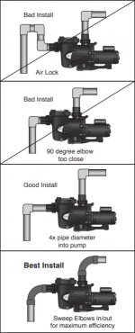
Here is what they show in the manual.
Water coming out of a 90 will be more turbulent than water going through a straight section of pipe.
It might help a little bit if the water velocity is above 6 feet per second, but I don't think that it makes any significant different difference when you have the strainer housing in front of the impeller.

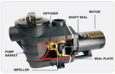
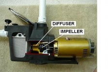
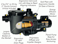
Here are some pump cutaways.
You can see the path that the water needs to take to get to the eye of the impeller.
Turbulence in any part of the water flow path decreases efficiency.
That’s why there are rules for water velocity and why many designers recommend sweep elbows instead of sharp 90 degree elbows.
In the Jandy installation diagram, they recommend the sweep 90 over even using straight pipe in front of the pump.
If you are doing multiple jobs, keep the velocity on the suction plumbing below 6 feet per second and use pressure rated sweep 90s instead of sharp 90s.


Thread Status
Hello , This thread has been inactive for over 60 days. New postings here are unlikely to be seen or responded to by other members. For better visibility, consider Starting A New Thread.


