Hi,
I went from a Jandy automation system to a Pentair Intellicenter I8SIC60 (vendor made a custom IC60 package for me).
I have:
Pentair VS Pump
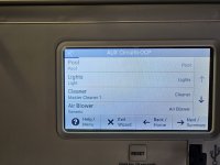
Jandy Booster (for cleaner) (aux2)
Raypak heater (Aux4)
Lights (Aux 1)
Spa air blower (aux 3)
IC60 salt generator
My pool has a spa & pool area
I did the installation of my Jandy in 2013 myself. This time during the renovation my electrician did the installation but am having some issues. I am following some youtube videos such as this one:
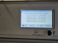
My Intellicenter has an intake & return on the board which is where i plugged the intellivalve modules. When I went through the setup wizard, i have valve A & valve B as an option but no intake or return valve selections available.
1. Intellivalves - I followed this video:
which shows how to program. The steps seem to be program the spa section, then the pool section, hit save & then goto auto - this makes sense to me.
- I just dont get why I dont see intake & return but do see A & B for the valve options in the software. The valves are plugged into the intake / return spots on the board.
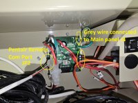
2. Wireless controller (Pentair Intellicenter Wireless Remote W/ Charging Cradle 522036 | PoolSupply4Less) - I got this so no one needed an app at the pool. I have it wired into Com port J5 (I have tried J4 also but didnt work). I have set the main unit & wireless unit to may different channels (24, 21, 19, etc) - I dont really get why it doesnt see my panel.
I have hard wired ethernet to the panel & can access everything online but would like to allow visitors to work the pool without me - I have no idea why it doesn't work.
- I dont see anything to 'link' the two.
Other item - hope it is not an issue BUT - my electrician had teh com port J4 connected to com port the intellichlor SCG port Jp2 . It does look like it should have been jumped over to the SCG board JP4 - currently the jumper (Com J4 is not connected to anything on the SCG board but i can move it to JP4).
Anyway I have other questions but the missing valve options & the wireless remote not connecting are confusing to say the least. I am very comfortable with wiring & setup - i was trying to make it easy on myself by hiring a professional but they are not really pool guys.
Thanks,
Rich
I went from a Jandy automation system to a Pentair Intellicenter I8SIC60 (vendor made a custom IC60 package for me).
I have:
Pentair VS Pump
Jandy Booster (for cleaner) (aux2)
Raypak heater (Aux4)
Lights (Aux 1)
Spa air blower (aux 3)
IC60 salt generator
My pool has a spa & pool area
I did the installation of my Jandy in 2013 myself. This time during the renovation my electrician did the installation but am having some issues. I am following some youtube videos such as this one:
My Intellicenter has an intake & return on the board which is where i plugged the intellivalve modules. When I went through the setup wizard, i have valve A & valve B as an option but no intake or return valve selections available.
1. Intellivalves - I followed this video:
- I just dont get why I dont see intake & return but do see A & B for the valve options in the software. The valves are plugged into the intake / return spots on the board.
2. Wireless controller (Pentair Intellicenter Wireless Remote W/ Charging Cradle 522036 | PoolSupply4Less) - I got this so no one needed an app at the pool. I have it wired into Com port J5 (I have tried J4 also but didnt work). I have set the main unit & wireless unit to may different channels (24, 21, 19, etc) - I dont really get why it doesnt see my panel.
I have hard wired ethernet to the panel & can access everything online but would like to allow visitors to work the pool without me - I have no idea why it doesn't work.
Other item - hope it is not an issue BUT - my electrician had teh com port J4 connected to com port the intellichlor SCG port Jp2 . It does look like it should have been jumped over to the SCG board JP4 - currently the jumper (Com J4 is not connected to anything on the SCG board but i can move it to JP4).
Anyway I have other questions but the missing valve options & the wireless remote not connecting are confusing to say the least. I am very comfortable with wiring & setup - i was trying to make it easy on myself by hiring a professional but they are not really pool guys.
Thanks,
Rich