Pool Panel Wiring Question

mzuri

0
Bronze Supporter
Mar 24, 2017
36
GA
Breakers: Siemens 40A GFCI at House Panel & 20 A GFCI at Hayward PL Subpanel

Current Wiring:
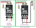
1566182031403.png

Does this look right? Specifically, with regard to the neutral path:

House Panel: Incoming Service Neutral - House Panel Neutral Bar - Pigtail to GFCI-Load Neutral Out to chlorinator subpanel (connected direct to GFCI )
Pool Sub Panel: Load Neutral out From House Panel - Into Subpanel Neutral Bar- Pigtail to GFCI-Load Neutral to 120 Volt Chlorinator Control (connected direct to GFCI )

Thank you
 
Neutrals look correct.

You don’t need a 40 A GFCI breaker in the house panel feed to the subpanel when the subpanel will have GFCI breakers.
 
Allen,

Are we sure??? I don't believe that you can have a 120 take off on a 220 GFCI breaker??? Won't it just pop the GFCI???

You know more about this than I do, but something just looks off..

Another question.. I was taught that you should not wire GFCI's in series.. I know you said the OP did not need it, and I agree, but is it allowed???

I'm sure you know more about this subject than I do, but I'd appreciate a second look.

Thanks,

Jim R.
 
The house panel needs a standard 220v breaker. The sub panel is where the GFIs will go.

If it's done like it's shown in the picture any 120v load will trip the house panel breaker. A GFI trip would almost be impossible to troubleshoot.

A 120v gfi circuit needs a 120v gfi breaker, you can't steal a leg off a 220v gfi breaker. That's exactly what a 2-pole GFI is designed to detect.
 
Last edited:
I don't believe that you can have a 120 take off on a 220 GFCI breaker??? Won't it just pop the GFCI???

I believe it will work but not 100% sure. Code says pumps should be on a dedicated CB so have never tried it.

Another question.. I was taught that you should not wire GFCI's in series.. I know you said the OP did not need it, and I agree, but is it allowed???

It is allowed but not recommended. If the main panel GFCI trips it will be difficult figuring out what device caused the trip. And the main panel GFCI is not protecting anything.

Best practice would be regular 40A CB in main panel; subpanel having 20A 240V GFCI CB for pump and 15A 120V GFCI CB for chlorinator.
 
What SWG is it?
Can it be wired 240?
Putting a 120 volt load on this type of breaker will work because the breaker accounts for current on all 3 wires.

That's why the load has to have the neutral connected to the breaker and not to the neutral bar.

Some hot tubs have mixed 120 and 240 volt components and the tub is fed by this type of breaker. See diagram.

Hot tubs with mixed voltage components (such as 120V ozonator and 240V heater) require 4-wire systems. This means they require an electrical circuit providing (2) hot wires, (1) neutral, and (1) ground wire.

I would make the main panel a standard breaker.

If the main breaker was gfci, it should work with mixed voltages and provide protection.

Note: Have all work designs and finished work approved by a licensed, qualified electrician to make sure that it meets all applicable standards.
 
Last edited:
The circuit breaker gfci works similarly to a clamp ammeter. For example, if you had L1, L2 and Neutral and you put a 240 volt, 10 amp load on the system, L1 and L2 would each carry 10 amps.

If you measure L1 or L2, you should read 10 amps on each leg. However, if you clamp over both lines at the same time, the current would read zero because the current's magnetic field in the forward direction cancels the current's magnetic field in the reverse direction.

If you then added a 120 volt, 5 amp load, you would measure 15 amps on one hot leg, 10 amps on the other hot leg and 5 amps on the neutral.

A clamp ammeter around any 2 or 3 wires will measure the net difference between current in both directions.

Putting the meter around all 3 wires should cancel and read zero amps.

As long as the neutral goes through the breaker, the total current in both directions should cancel.

So, a breaker doesn't really measure current and compare to make sure that the current is the same. It works on a cancelling effect.

As long as the current in both directions cancels, the breaker won't trip.
 
Guys - You are awesome!

Makes sense now. Per recommendations: I am going to have a regular breaker at the Main panel and wire up 2 GFCIs at the subpanel - 240 v for the VSP and a separate 120 V for the control circuit. Will report back and once I am organized I will write all this up
 
What SWG will you have?
It can't be wired 240?

You need to make sure that the SWG power gets turned off anytime that the pump is off. You can use a timer to control power to the SWG. Set the time to be within the pump runtime window.

I don't see a problem powering the SWG from the pump breaker whether it is 120 or 240. You can use a separate breaker if you want.
 

Enjoying this content?

Support TFP with a donation.

Give Support
The circuit breaker gfci works similarly to a clamp ammeter. For example, if you had L1, L2 and Neutral and you put a 240 volt, 10 amp load on the system, L1 and L2 would each carry 10 amps.

If you measure L1 or L2, you should read 10 amps on each leg. However, if you clamp over both lines at the same time, the current would read zero because the current's magnetic field in the forward direction cancels the current's magnetic field in the reverse direction.

If you then added a 120 volt, 5 amp load, you would measure 15 amps on one hot leg, 10 amps on the other hot leg and 5 amps on the neutral.

A clamp ammeter around any 2 or 3 wires will measure the net difference between current in both directions.

Putting the meter around all 3 wires should cancel and read zero amps.

As long as the neutral goes through the breaker, the total current in both directions should cancel.

So, a breaker doesn't really measure current and compare to make sure that the current is the same. It works on a cancelling effect.

As long as the current in both directions cancels, the breaker won't trip.


Great explanation. Siemens shows that clamp over the 3 lines in it's wiring diagram. It's the circle in the picture.

 
  • Like
Reactions: JamesW
What SWG will you have?
It can't be wired 240?

You need to make sure that the SWG power gets turned off anytime that the pump is off. You can use a timer to control power to the SWG. Set the time to be within the pump runtime window.

I don't see a problem powering the SWG from the pump breaker whether it is 120 or 240. You can use a separate breaker if you want.
Its a Hayward PL-PLUS chlorinator with a subpanel - to accommodate the 240 volt breaker for the pump and needs a 120 volt supply with neutral for the control circuit . Had to redo the wires simply for the neutral but that wil come in handy for future electrical yard projects as the subpanel is rated for 100VA.
1566241407868.png

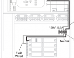
Last question - should I wire the neutral off the bar as shown (that may be showing a non GFCI setup) or from the GFCI breaker as indicated on the 1-pole Siemens diagram ( is the neutral a pass through?)
 
With the Siemens GFCI CB the pigtail from the CB goes to the neutral bus bar. The neutral from the load connects to the CB. See the pic in post #11.
 
  • Like
Reactions: mzuri
Ok, I would put the pump on its own gfci breaker and control the pump speed through two relays. Set the controller to two speed pump.

Put the control panel on its own 120 volt breaker (either regular or gfci).

It would have been better if you used a Hayward variable speed pump, but you can make the v-green work.
 
The ProLogic will communicate with a Hayward variable speed pump.

It won't communicate with the V-green.

You can use the relays in the ProLogic to control two speeds in the V-green motor.
 
Thread Status
Hello , This thread has been inactive for over 60 days. New postings here are unlikely to be seen or responded to by other members. For better visibility, consider Starting A New Thread.