Pool pad automation/monitoring

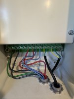
Show us the inside wiring of your Aquaswitch.

You also have a box marked Intellicomm. Where is that wired into?

1724687063683.png
 
IntelliConnect will not work for you.

You need 3 relays for the SWG, booster pump, and lights. The IntelliConnect only has two relays.

And the Intelliconnect will not work with pH dosing equipment.

For Pentair you need the IntelliCenter Lite.
And my existing intellicomm will NOT run the SWCG if I just added that to it?

Just seeing what all routes I can go..
 
The intellicomm has the wire with their proprietary or special connector coming out of the pump then I believe it is what sends the signal to ramp up the pump when the heater comes on then run for 5 minutes on cool down and sends the signal to the booster pump when the vacuum/cleaner runs
 
And my existing intellicomm will NOT run the SWCG if I just added that to it?

All the Intellicom does is give you analog relay speed control of your digital VS pump.

I want to see where the Inetllicomm is connected to.

Post #57 is the inside of the aquaswitch box, sir
I asked to see the INSIDE WIRING of the Aquaswitch. Remove the panels to show the wiring inside.
 
The intellicomm has the wire with their proprietary or special connector coming out of the pump then I believe it is what sends the signal to ramp up the pump when the heater comes on then run for 5 minutes on cool down and sends the signal to the booster pump when the vacuum/cleaner runs
Yup, that is the digital side of the Intellicomm wiring.

Now where and how is the Intellicomm wired to know when the heater comes on or the booster pump is on?
 
I will get photos. Sorry I don’t know more. We moved in here in may and I’ve been trying to learn as much as I can since then.

I believe it all runs from the intellicomm down to the aqua switch other than the one connector/wire that runs over to the pump.
 
I believe it all runs from the intellicomm down to the aqua switch other than the one connector/wire that runs over to the pump.

The devil is in the details.

Got to see the actual wiring not what you believe.
 
  • Like
Reactions: uraceulose
Hope these help. Please let me know if not and I’ll figure out what to do to get the right information
 

Attachments

  • IMG_8197.jpeg
    IMG_8197.jpeg
    417.3 KB · Views: 8

Enjoying this content?

Support TFP with a donation.

Give Support
Hope these help. Please let me know if not and I’ll figure out what to do to get the right information
It is really not helpful when I just see a jumble of wires, most of which go off frame.

You need to show clear enough pictures such that wires can be followed from one end to the other if you want us to try and help explain how your system works.

Or hire someone who can examine your system on-site and figure it out.
 
I’m trying here but it says photo too large so I’ve cropped it down about 5 times. Will try to get some better ones..
 
I’ll try to just take a video because it’s really hard to follow the wires when they’re running through the conduit from the one box into the switch
 
I’m trying here but it says photo too large so I’ve cropped it down about 5 times. Will try to get some better ones..

Resize the pic for lower resolution but don't crop it. Or reduce the resolution of the pics your phone is taking. Get the pics below about 2MB and the server will like them.

Turn off HDR if it is on in your phone camera.

 
I’ll try to just take a video because it’s really hard to follow the wires when they’re running through the conduit from the one box into the switch

No, don't do a video. Wiring cannot be easily studied on a video.

Do a series of pictures that methodically follows the wires.
 
Ok. Please bear with me. I will keep digging back as far as you tell me to.

The green/yellow pairs coming out of the intellicomm box run one pair into the heater and the other pair over to the connector that plugs into the pump.

The blue pair runs into the aqua switch box our of the intellicomm box as well as the red pair run easy pair into the transformers.

The relays all run from the relay port to their respective transformers.
 

Attachments

  • IMG_8205.jpeg
    IMG_8205.jpeg
    500.3 KB · Views: 11
  • IMG_8206.jpeg
    IMG_8206.jpeg
    269 KB · Views: 12
  • IMG_8207.jpeg
    IMG_8207.jpeg
    428.2 KB · Views: 91
  • IMG_8208.jpeg
    IMG_8208.jpeg
    403.3 KB · Views: 11
Can anyone tell me based on these photos if I can add a swg to that existing open relay slot?

And can I add intelliconnect or do I need to go to a full on IntelliCenter in order to go automated?
 

Enjoying this content?

Support TFP with a donation.

Give Support
Thread Status
Hello , This thread has been inactive for over 60 days. New postings here are unlikely to be seen or responded to by other members. For better visibility, consider Starting A New Thread.