Pool light stopped working years ago. Read on...

SaltLife97

Member
Feb 7, 2016
17
Melbourne, Florida
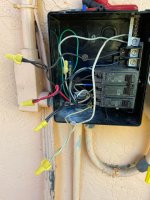
So our pool light hasn't worked for about three 1/2 years and I finally decided to get around to testing the voltages first at the junction protruding from the ground next to the pump. No voltage on the white and red wires going to the light. So I open the original PX300 transformer and the breaker box next to it. Two breakers: one dual for the pump and one single breaker for the (light?). Nothing tripped. So I test voltage going into side where the breakers click onto the metal rail. I'm getting 120v from the house to the rail (duh, because the pump works). So I check voltage coming out of the single breaker...120 volts. Ok. checking the two black wires that should show 12v from the transformer? Nada. So I replace the transformer with a new PX300. Flip the light breaker...nothing. Alrighty.

The thing is, the wire from the single breaker disappears back into the conduit that supplies power from the house and disappears up into the home. But there is also a black wire coming from that same conduit. The white wire goes to the metal rail on the breaker side and is twisted to the white wire going to the transformer. The black wire from the house is twisted to a black wire leading to the transformer. So now I'm stumped. It is almost like it bypasses any circuit breaker and just feeds power directly to the transformer. Could this mean there is a breaker in the main panel of the house that this black and white wire are fed power to??? Because the only breaker labeled anything pool is "Pool Pump".
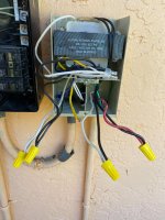
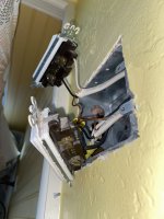
Pool.jpg


Pool2.jpg
 
Last edited:
I should mention that between the black wires (right beneath the red and black wires) coming into the black breaker box and the white wire coming from the metal breaker rail and into the conduit to the transformer show 0.50 volts o_O And 0.3 volts when tripping the bottom breaker.
 
To bump this up I actually discovered the light switch to turn the light on INSIDE the home is not getting 120v. I cannot find the breaker responsible for this circuit since every one that I shut off has something it was affected by. Wires don't just break inside walls or attics. Trying to access the wire from the attic area is no go since that part of the home isn't that accessible at all.
 
Wires don't just break inside walls or attics. Trying to access the wire from the attic area is no go since that part of the home isn't that accessible at all.
Ah but they do. Hang any pictures or shelves over the past couple of years? Fix any plumbing? Make any wiring changes?

PLEASE BE CAREFUL. Mains power can kill.

You have generally the right approach (except maybe you pulled the trigger too early on he new transformer). Use a meter to trace circuits from one or both ends, verifying with either voltage checks if the power's on or continuity (in ohms) if it's not.

To rule out the complete low voltage circuit, temporarily disconnect and rewire the transformer primary to a plug. Power that with an extension cord. If you get light, you can focus entirely on the primary 120v circuit, which it seems you already know has a problem.

When you've ruled out all possibilities but one, you know where the problem is.
 
To bump this up I actually discovered the light switch to turn the light on INSIDE the home is not getting 120v. I cannot find the breaker responsible for this circuit since every one that I shut off has something it was affected by. Wires don't just break inside walls or attics. Trying to access the wire from the attic area is no go since that part of the home isn't that accessible at all.
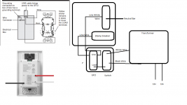
Are there other wires in the box in the house with the switch? It looks like the bottom breaker in the pool panel has a white wire taped black going to it which then looks like it goes back into the conduit going to the house. Then the black appears to come from that same conduit and goes to the transformer making appear as if that may just be a switch loop ( relabled white to load side of the switch and black to lone side circling back) Did you test power at that single breaker? If it works, theoretically you could abandon the two wires circling back to the house:
disconnect the flex coming from the transformer
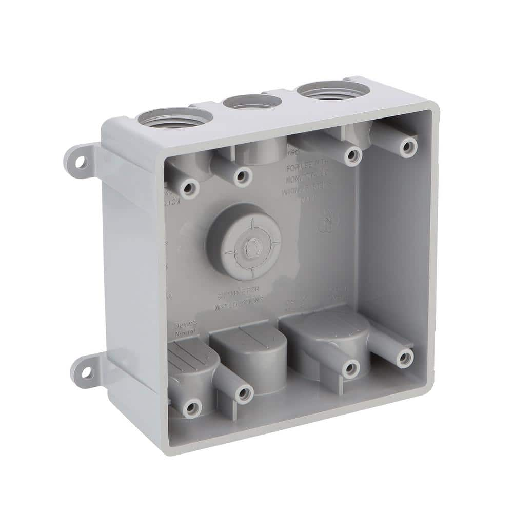
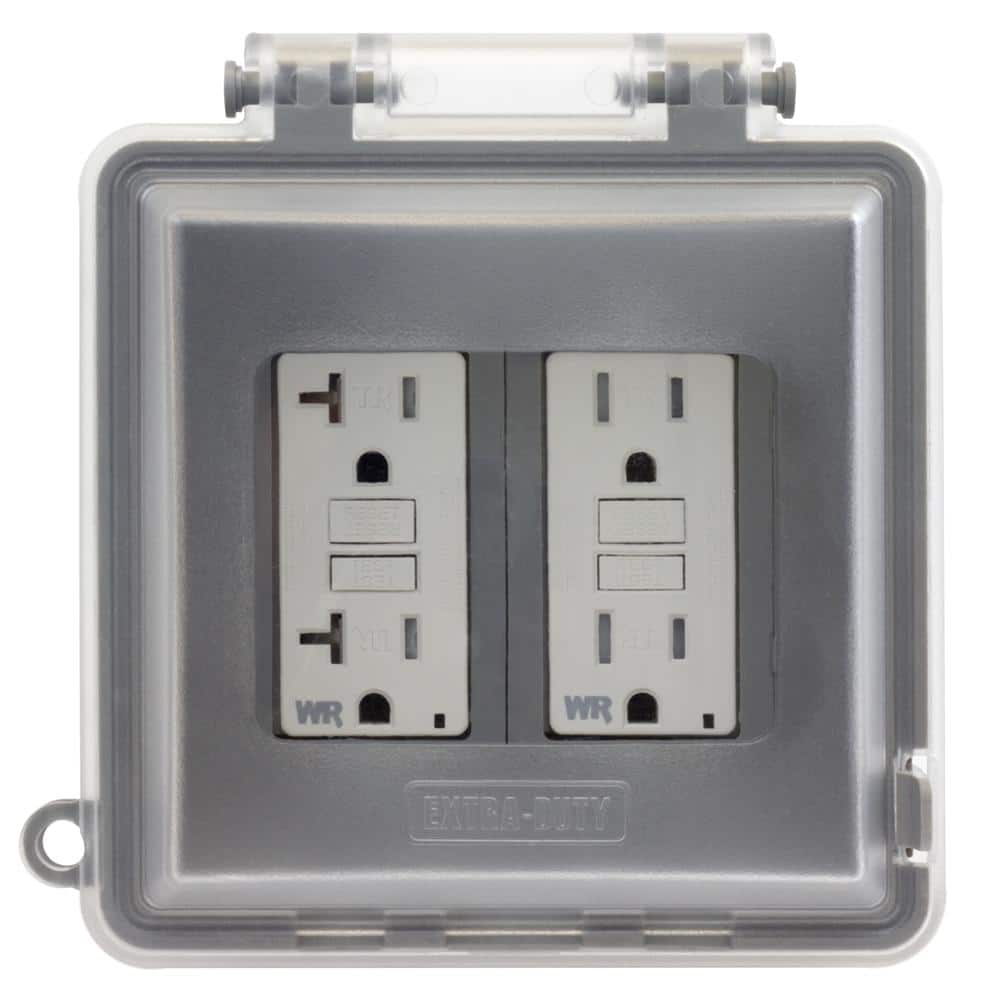
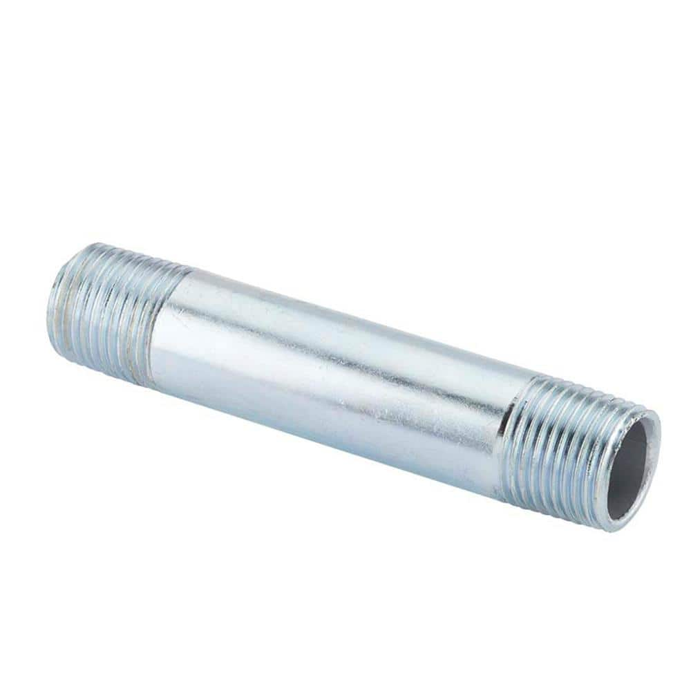
add a conduit nipple to a two gang outdoor box below the pool subpanel
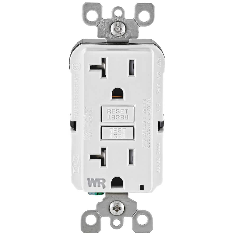
Install a gfci outlet for the now empty bottom breaker
Go from the load side of the gfci to a smart switch
Attach the flex from the transformer to the new two gang box and connect to the smart switch.
 
Are there other wires in the box in the house with the switch? It looks like the bottom breaker in the pool panel has a white wire taped black going to it which then looks like it goes back into the conduit going to the house. Then the black appears to come from that same conduit and goes to the transformer making appear as if that may just be a switch loop ( relabled white to load side of the switch and black to lone side circling back) Did you test power at that single breaker?
This would make the most sense. I was having trouble following OP's description of what was happening until you laid this out.

--Jeff
 
  • Like
Reactions: SaltLife97
Are there other wires in the box in the house with the switch?
Yes; There is the pool deck floodlight switch next to it but not wired to the pool underwater light switch. However both share a copper ground and that is it. That switch works fine and the breaker it uses is known.
Did you test power at that single breaker? If it works, theoretically you could abandon the two wires circling back to the house:
I did! When the breaker is ON, that white wire wrapped in black saw 120v going to the box's ground. Flipping OFF it went away. So it was appear as though that part works. I had to read your install instructions a few times but that's just how I learn ;). I understand what you're saying, and it makes sense because I have an active pool pump circuit utilizing that box with apparently a redundant 20amp single breaker. I'll be metering every wire I touch and cutting power to the pump via the main breaker and the pool breaker. Safety I understand, I'll give this a go.
 
Yes; There is the pool deck floodlight switch next to it but not wired to the pool underwater light switch. However both share a copper ground and that is it. That switch works fine and the breaker it uses is known.
Are the deck light and pool light switch in the same box? Post of photo of the content of that as well. Sounds like they may feed off of the same power/breaker (the black wrapped white wire) if that is the case you will need to modify my instructions some however that has the potential to leave the "broken" connection hot (less than ideal)
 
Are the deck light and pool light switch in the same box? Post of photo of the content of that as well. Sounds like they may feed off of the same power/breaker (the black wrapped white wire) if that is the case you will need to modify my instructions some however that has the potential to leave the "broken" connection hot (less than ideal)
They are. The switch above and facing towards the wall is the pool light which I'm not seeing 120v at. And the One facing downward is the flood light. They share a copper ground.
 

Enjoying this content?

Support TFP with a donation.

Give Support
They are. The switch above and facing towards the wall is the pool light which I'm not seeing 120v at. And the One facing downward is the flood light. They share a copper ground.
Ok a few questions to make sure I don't steer you wrong, I beleive my brain has the problem and a couple solutions to correct this problem and optionally prevent future ones
1. Post pictures of the two switchboxes
2. By any chance was the switch replaced for the deck lighting in the past?
3. Does the pool light work sometimes or never ?
4. Have you checked the pool light switch for power with the deck light switch also on.
5. Any interest now or in the future of swapping either of these switches for smart switches?

I'm not as adept at the line drawing as you so when I get home I'll revise your drawing and post it here.
 
Last edited:
Whoops! I thought I had uploaded the switch box. My bad!
IMG_1457.jpeg

Also, no the deck light switch was never replaced. The pool light worked always for the 8 out of 11 years we lived here, but one day it never turned the transformer on and that was that. Yes I have checked the pool light switch with deck power on, however in the past the two were isolated from each others operation and neither required the other to be ON to function. And if I'm going the bypass route after all outside and do the GFCI and switch install, It'll definitely be a smart switch as your instructions mentioned above. The deck light rarely gets used so I'm fine with keeping that a dumb paddle switch.

The top switch as mentioned before is the pool under water light switch. The main garage breaker panel has its own POOL PUMP dual-style breaker which controls all power to the black pool breaker box. That POOL PUMP breaker disconnects full power to the pool breaker box including the 20amp breaker on it. So, to me it seems like that whole POOL PUMP circuit is separate from the inside light switch circuit. Otherwise the pump wouldn't work either. So far it seems your bypass idea off that 20amp external breaker would work if I understood correctly the wiring of the GFCI and smart switch.

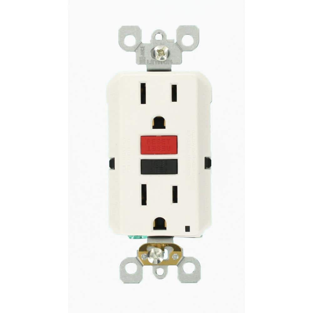
This is what I would use:

 
Last edited:
Something odd is going on with the pool light switch. It's using both the hot and neutral which leads me to think that its only one leg of the circuit and you wont see voltage. Try turning it on and seeing if you get voltage between either wire and ground or the hot wire on the switch next to it.
 
Whoops! I thought I had uploaded the switch box. My bad!
View attachment 473603

Also, no the deck light switch was never replaced. The pool light worked always for the 8 out of 11 years we lived here, but one day it never turned the transformer on and that was that. Yes I have checked the pool light switch with deck power on, however in the past the two were isolated from each others operation and neither required the other to be ON to function. And if I'm going the bypass route after all outside and do the GFCI and switch install, It'll definitely be a smart switch as your instructions mentioned above. The deck light rarely gets used so I'm fine with keeping that a dumb paddle switch.

The top switch as mentioned before is the pool under water light switch. The black wire is what I assume comes from the conduit outside to the black breaker box and the white disappears up to the attic if I'm not mistaken. It seems there is a disconnect between the outside 20 amp breaker to this switch. The main garage breaker has its own POOL PUMP dual-style breaker which controls all power to the black pool breaker box. That breaker disconnects full power to it and also feeds the 20amp breaker. So it seems like it is separate from the inside light switch circuit otherwise the pump wouldn't work either. So far it seems your bypass idea off that 20amp external breaker would work.

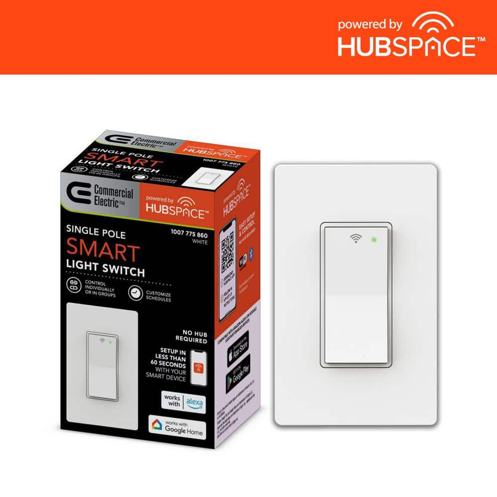
This is what I would use:

Ok cool so to confirm and based on the look, the deck lights are on a completely different circuit. Both the black and white are coming from one romex. This is likely the black wire feeding your current transformer and the white wire taped black to the breaker. None of this looks like it was installed by an electrician as there are a ton of issues but you should be able to resolve the majority of them now.
Materials:
you want this GFCI, it should be 20 amp and it must be weather resistant
The switch you linked should work fine.
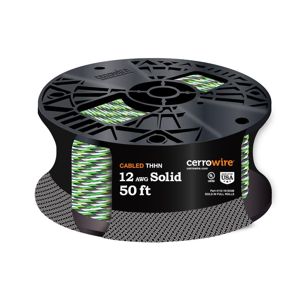
At my HD or lowes they have this by the foot, I would get 10ft.
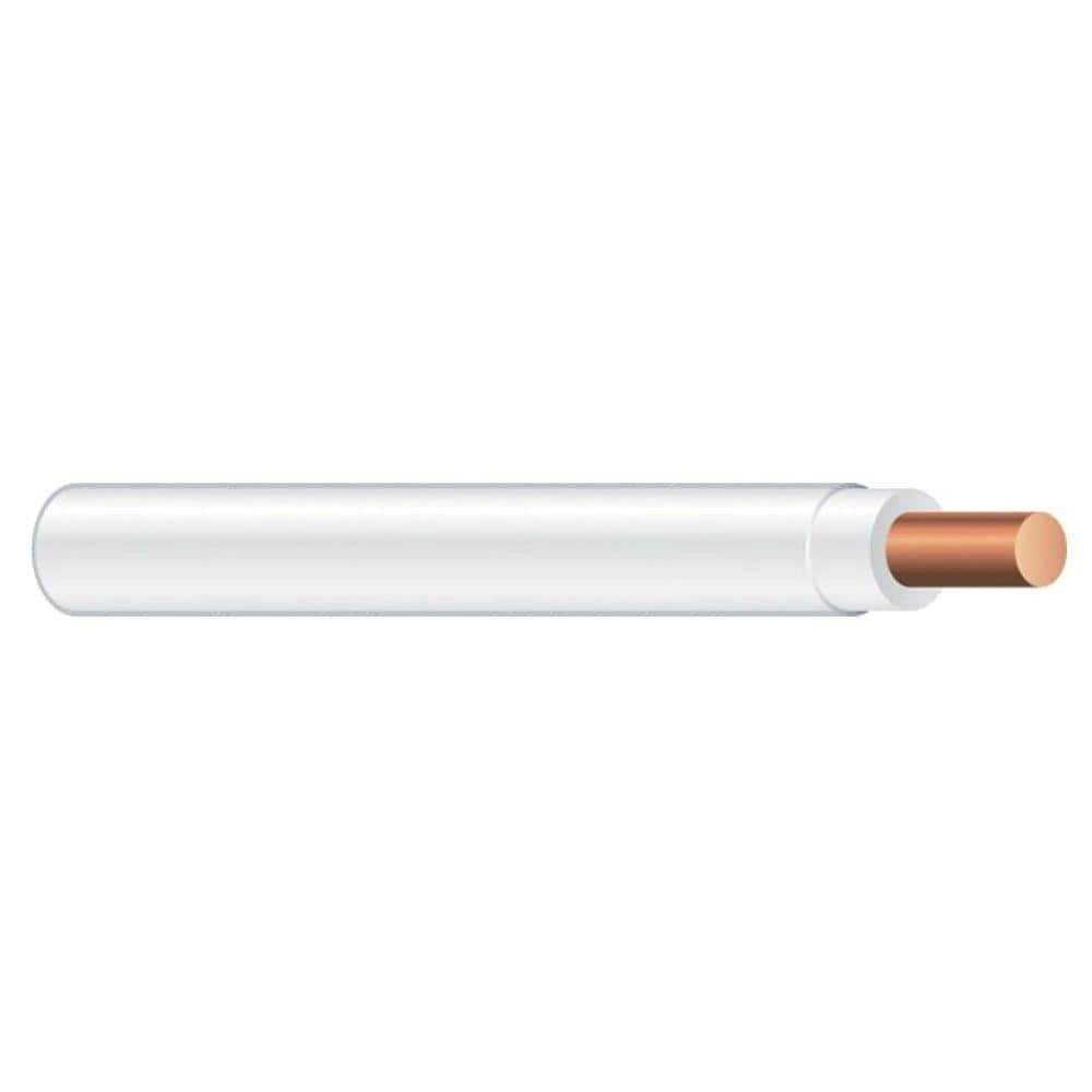
Alternatively get 10ftea of white , black and green thwn
1 2 gang weatherproof box, i prefer pvc as you dont need to ground the box
2 gang in use cover
3/4 nipple, pvc or rigid pipe
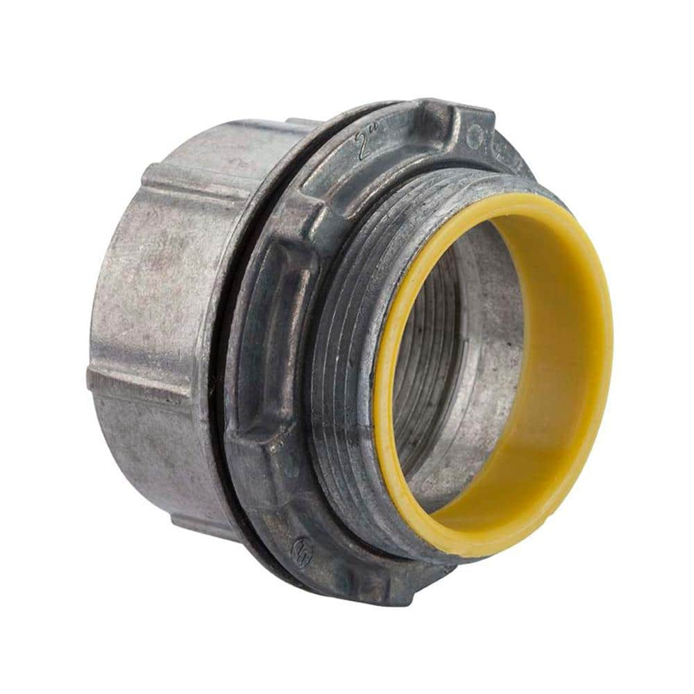
if you use rigid youll need a water tight hub for the enclosure side
you should be able to use the existing flex but pull new thwn wire into it (romex is not allowed in wet or damp locations and conduit is at a min considered damp)
youll also need either some wire nuts or lever nuts (best for DIY) or ideal 33 push in connectors

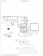
You will end up abandoning the 14/2 romex going back to the switch in the house (ie the white with black tape and black currently going to the transformer) so cap them off.Epson_02162023132611.jpg
 

Attachments

  • Epson_02162023131251.pdf
    625 KB · Views: 4
Last edited:
Ok took my glasses off and looked closer at the pics you provided. Here's what i see. The hotwire off the breaker (white woth black tape) is run into the pull box on the left of the panel. I would bet its spliced in there so take the cover off and check. I willing to bet this is going to one side of the switch in the house.

The black hotwire coming out of the pull box and spliced into the wiring for the transformer is the other side of the switch.

After verifying there are no loose/broken connections in the pull box, Try connecting the transformer directly to the breaker by disconnecting the white/black tape wire from the breaker and connecting the black hot wire going to the transformer and see if it works when the breaker is on.
 
Whoops! I thought I had uploaded the switch box. My bad!
View attachment 473603

Also, no the deck light switch was never replaced. The pool light worked always for the 8 out of 11 years we lived here, but one day it never turned the transformer on and that was that. Yes I have checked the pool light switch with deck power on, however in the past the two were isolated from each others operation and neither required the other to be ON to function. And if I'm going the bypass route after all outside and do the GFCI and switch install, It'll definitely be a smart switch as your instructions mentioned above. The deck light rarely gets used so I'm fine with keeping that a dumb paddle switch.

The top switch as mentioned before is the pool under water light switch. The main garage breaker panel has its own POOL PUMP dual-style breaker which controls all power to the black pool breaker box. That POOL PUMP breaker disconnects full power to the pool breaker box including the 20amp breaker on it. So, to me it seems like that whole POOL PUMP circuit is separate from the inside light switch circuit. Otherwise the pump wouldn't work either. So far it seems your bypass idea off that 20amp external breaker would work if I understood correctly the wiring of the GFCI and smart switch.

This is what I would use:

Out of curiosity and you know, simplest solution often being correct, it is possible the switch itself is bad. Have you tried to remove the pool light switch and just tie those two wires together (the white and black at the single switch are just being uses as a switched hot leg, they are not hot and nuetral).
 
Something odd is going on with the pool light switch. It's using both the hot and neutral which leads me to think that its only one leg of the circuit and you wont see voltage. Try turning it on and seeing if you get voltage between either wire and ground or the hot wire on the switch next to it.
Yeah it seems like whoever installed this switch was NOT an electrician and did some hoopty bull----. In fact, I don't even know how this house passed inspection (oh wait this is Florida and basically it really IS lawless out here) since much of the wiring looks like sketchy trash in the attic too. Turning the switch on or off yielded no results and disconnecting the wires and checking continuity between them showed no continuity either. Definitely seems like a break in the circuit somewhere inside the home. I initially thought maybe the light bulb in the pool was not completing the circuit but we had tried a brand new bulb in the past and the light didn't come on. I guess it is back to wiring a new circuit outside.

Also, check for continuity between the wires in the switch and the wires leaving the transformer box.
The transformer has continuity between the transformer and the junction by the pump ( testing underground wire integrity for cuts or disconnects) and there it full continuity. I
I'll check for continuity on the wires going to the pool light too. Also I checked that side box you mentioned where the wires disappear into the conduit to the home....it is some USELESS cover that just show the wires running into the romex and into the home lol. Literally no reason for that to have an access port since nothing it spliced there. Almost looks like just an additional part just to make an extra buck for the original home owner back in the day. A simple conduit WITHOUT this access port would've done the same.
 

Enjoying this content?

Support TFP with a donation.

Give Support
Thread Status
Hello , This thread has been inactive for over 60 days. New postings here are unlikely to be seen or responded to by other members. For better visibility, consider Starting A New Thread.