@Qcp800
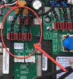
1. Have you plugged the little 2-pin connectors from the relays into the i8 daughter card?

2. Check to insure that power from the applicable breaker(s) are connected properly to the relays.
3. Check to insure that the devices that you are attempting to control via the relays are connected to the relays properly.
i.e.
(For the examples below, terminal compression screws are numbered from left to right.)
For 120VAc devices - The 120Vac power lead from the breaker should be connected to terminal screw #1 of the relay and the power lead (black), should be connected to terminal screw #2.
For 240Vac devices - The two power leads from the 2-pole breaker should be connected to terminal screws #1 and #3. The two power leads from the device (usually red and black), should be connected to terminal screws #2 and #4.
In other words:
There are four (4) terminal compression screws on the forward bottom of the relay, each of which allows two leads to be connected.
The
1st and the
3rd (left-to-right) compression screws (
LINE SIDE) are designated to be wired to the associated circuit breaker and consequently remain continuously energized (HOT), unless the applicable circuit breaker is “flipped” off manually or tripped for some reason.
The
2nd and the
4th compression terminal screws (
LOAD SIDE) are designated to be wired to the line-voltage item itself (NOT applicable to IntelliFlo pumps.) The
LOAD SIDE terminals are only energized when the circuit has been turned on through the automation system either manually or through a scheduled event.
The power relay is designed to control either 240 Vac or 110 Vac equipment and devices.
If the relay is used to control a 240 Vac device - The
1st and
3rd compression terminal screws (
LINE SIDE) are used to connect each leg of the 240 Vac circuit to the associated circuit breaker.
The
2nd and
4th compression terminal screws (
LOAD SIDE) are used to connect each leg of the 240Vac circuit to the applicable line-voltage device.
If the relay is used to control a 120 Vac device - Then the
1st compression terminal screw is used to connect the 120 Vac circuit (“black” power leg) to the applicable single-pole breaker.
The
2nd compression terminal screw is used to connect the 120 Vac circuit (“black” power leg) to the applicable line-voltage device (light, low voltage lighting transformer, etc.). The “white” neutral leg is connected to the neutral bus bar or in the case of GFCI circuit breakers, to the terminal screw located on the breaker for that purpose and the white pigtail from the breaker connects to the neutral bus bar.
For more detailed information, please refer to "
IntelliCenter Daughter Card (Personality Card)" in this link:
IntelliCenter Quick Reference/Information Guide
and "
Power Relay (P/N 520106) Filter Pump (FLTR) / Auxiliary (Aux) Line-Voltage (power) Relay" in this link:
IntelliCenter Quick Reference/Information Guide
Caution: If you are attempting to troubleshoot/make modifications to electrical connections within the IntelliCenter Load Center, please remember to
de-energize your Load Center at the house main electrical panel whenever removing the Load Center "High Voltage Cover Panel (“Dead Front” panel)". Check to insure that power has been removed with the use of a working multi-meter. If you feel you do not posses the necessary skill sets/qualifications to do this type of work, please seek out a licensed pool electrician in order to prevent injury or worse.
Thanks..
r.


