
Pentair IntelliBrite 5G Defect
- Thread starter Dirk
- Start date
You are using an out of date browser. It may not display this or other websites correctly.
You should upgrade or use an alternative browser.
You should upgrade or use an alternative browser.
santacruzpool
Gold Supporter
Side Note: Jandy now has a new water cooled LED showing on their site.
I have had 3 sets of the Jandy Nicheless lights fail in just over 3 years. So they certainly could use a improved product.
I have had 3 sets of the Jandy Nicheless lights fail in just over 3 years. So they certainly could use a improved product.
FrankAZ
0
Its interesting - I hadn't seen this post until now - I have a board that also failed on U1 (and I've had the replacement chip for a few months, but, haven't installed it since I found burned traces on a few of the pins also - but - its clear "water intrusion" was part of the problem. (I got the board as a sample project off offer up for 20 to see how it was built)
I want to do a full tracing of the board pins once I have more time. I may also happen to have a DIP version of the PIC24FJ here also that I want to attempt to load up.
I want to do a full tracing of the board pins once I have more time. I may also happen to have a DIP version of the PIC24FJ here also that I want to attempt to load up.
- Nov 12, 2017
- 12,647
- Pool Size
- 12300
- Surface
- Plaster
- Chlorine
- Salt Water Generator
- SWG Type
- Pentair Intellichlor IC-40
Keep goin' everybody! I want to be able to fix my board for $1 when it fries out of warranty next year!
I finally got around to playing with the 2nd Intellibrite board that had J4 torn off... for the price of this board I would at least expect a terminal block that's screwed down securely, instead of surface mount quick connects!! Anyway, I don't have an Intellibrite in my pool so I don't know if my "fixed" version will fit in the housing, but it functions.
Looking at the board with J4/J1 in the top right, J4 connects to the left side of D23 and to the top right of D32 (I believe D32 is an optocoupler that tells the pic when the power is on). The hand-drawn red line in the photo below shows the connections to J4 that I had to repair...

In my fix, the trace leading to D32 was still mostly in tact but it tore off of the board between J4 and F1, so I soldered a jumper from the remaining trace to D23. The jumper is covered in glue to hold it down...

The parts on this board are difficult to solder to because they're all sitting on a giant heat sink that sucks up your soldering iron's heat. I did finally get a good solder joint onto D23, but I also ran the replacement wire/quick connect through the capacitors so I could glue it down and give it a better chance of staying put.

Looking at the board with J4/J1 in the top right, J4 connects to the left side of D23 and to the top right of D32 (I believe D32 is an optocoupler that tells the pic when the power is on). The hand-drawn red line in the photo below shows the connections to J4 that I had to repair...
In my fix, the trace leading to D32 was still mostly in tact but it tore off of the board between J4 and F1, so I soldered a jumper from the remaining trace to D23. The jumper is covered in glue to hold it down...
The parts on this board are difficult to solder to because they're all sitting on a giant heat sink that sucks up your soldering iron's heat. I did finally get a good solder joint onto D23, but I also ran the replacement wire/quick connect through the capacitors so I could glue it down and give it a better chance of staying put.
- Nov 12, 2017
- 12,647
- Pool Size
- 12300
- Surface
- Plaster
- Chlorine
- Salt Water Generator
- SWG Type
- Pentair Intellichlor IC-40
I need a translation! It sounds like what you're saying is: the LEDs are fine. It's not even the other components that are frying? But rather the traces are failing? What, the LEDs heat everything up so much that even the traces are melting off?
Does anything else on that board get very hot? Could they have mounted the LEDs on a daughter card, elevated off the rest of the board, with some sort of heat sink in between them? Something like that? Instead of really solving this, they just strapped on a thicker slice of copper underneath. So they wouldn't have to retool everything? Is the extra copper helping the problem, or just serving to better channel the heat to parts that can't withstand it?
Does anything else on that board get very hot? Could they have mounted the LEDs on a daughter card, elevated off the rest of the board, with some sort of heat sink in between them? Something like that? Instead of really solving this, they just strapped on a thicker slice of copper underneath. So they wouldn't have to retool everything? Is the extra copper helping the problem, or just serving to better channel the heat to parts that can't withstand it?
Hey Dirk,
I have two boards on my bench, #1 and #2... #1 has the small aluminum heat-sink and a burned out LED driver (failed from overheating). #2 has the thick copper heat-sink and would be fine except the installer ripped J4 off during installation.
The LEDs on #2 are fine and the traces failed from the mechanical stress of attaching/removing a quick connect to it (I don't think heat will affect the traces on the copper boards). I figured #2 would work if I could fudge the J4 connection, so that's what I did in the photos above.
I still plan to repair #1 and then take temperature readings on both, but I won't do that until I get a hot air rework station (coming soon) to do the LED driver removal/replacement.
Incidentally, I saw a board with a torn off J4 on eBay for 40 bucks... if my fix would fit in the housing, an enterprising person could have themselves a cheap replacement!
- Nov 12, 2017
- 12,647
- Pool Size
- 12300
- Surface
- Plaster
- Chlorine
- Salt Water Generator
- SWG Type
- Pentair Intellichlor IC-40
Hey Dirk,
I have two boards on my bench, #1 and #2... #1 has the small aluminum heat-sink and a burned out LED driver (failed from overheating). #2 has the thick copper heat-sink and would be fine except the installer ripped J4 off during installation.
The LEDs on #2 are fine and the traces failed from the mechanical stress of attaching/removing a quick connect to it (I don't think heat will affect the traces on the copper boards). I figured #2 would work if I could fudge the J4 connection, so that's what I did in the photos above.
I still plan to repair #1 and then take temperature readings on both, but I won't do that until I get a hot air rework station (coming soon) to do the LED driver removal/replacement.
Incidentally, I saw a board with a torn off J4 on eBay for 40 bucks... if my fix would fit in the housing, an enterprising person could have themselves a cheap replacement!
Assuming that's all that wrong with it!
OK, so heat didn't affect the traces of #2, the replacement process did. Why was there mechanical stress? Was there something wrong with the board, so they were taking out and putting it back in a lot? I'm confused why that was an issue, and why that ebay board apparently was subjected to the same treatment. Does that connector rip out the first time you try and remove the wire from it?
For the board I "repaired", I was told that the tech installed the board and it did not work because the transformer was actually the faulty part, and when he pulled off the wires to remove the board the J4 connector ripped off with it. It was a new board straight out of a sealed package.
Since the J1 and J4 connectors are surface mount, they're depending on the adhesion of the trace to the board substrate (a copper or aluminum plate) to handle the stress of connection/removal. I just looked at the manual and it even says to be careful removing the J1 and J4 connectors. Every other connector I've seen Pentair use (excepting the firmware connectors) are either through-hole or screw connectors, and they probably should have done the same here.
Since the J1 and J4 connectors are surface mount, they're depending on the adhesion of the trace to the board substrate (a copper or aluminum plate) to handle the stress of connection/removal. I just looked at the manual and it even says to be careful removing the J1 and J4 connectors. Every other connector I've seen Pentair use (excepting the firmware connectors) are either through-hole or screw connectors, and they probably should have done the same here.
- Nov 12, 2017
- 12,647
- Pool Size
- 12300
- Surface
- Plaster
- Chlorine
- Salt Water Generator
- SWG Type
- Pentair Intellichlor IC-40
I think the people that engineer stuff and the people that use stuff should get together every so often. Maybe have a little chat once in a while...

- Dec 17, 2017
- 667
- Pool Size
- 36000
- Surface
- Fiberglass
- Chlorine
- Salt Water Generator
- SWG Type
- Astral Viron eQuilibrium EQ45
Since the J1 and J4 connectors are surface mount, they're depending on the adhesion of the trace to the board substrate (a copper or aluminum plate) to handle the stress of connection/removal.
That is simply poor design.
Normally the PCB would be designed with a through plated via at those points so there would be no way they would pull off like they have.
With regards to the LED driver getting too hot - Is there any free room on top of the IC to add additional heat sinking capacity?
Good job on the repair so far - The hot air station will be beneficial.
Hey Costas,
Absolutely right about through plated vias!
As far as heatsinks on top of the IC... I was going down that road in another post but I don't have a housing so I don't know how much clearance there is. I wouldn't use a "stick-on" or adhesive heat sink because it will likely fall off... but if there was something that could be securely mounted and still fit it in the housing it could only help. I bet someone could mill up a small heatsink that could clamp onto the driver and the plate.
Once I get the driver on my #1 board (with the thinner aluminum plate) replaced I plan to run them both in sealed enclosures, log the temperatures and monitor them with a thermal camera to see what gets hottest.
- Dec 17, 2017
- 667
- Pool Size
- 36000
- Surface
- Fiberglass
- Chlorine
- Salt Water Generator
- SWG Type
- Astral Viron eQuilibrium EQ45
I wouldn't use a "stick-on" or adhesive heat sink because it will likely fall off...
You could opt for something simple like some copper plate etc - that would probably enough to take the edge off the heat being generated within the driver.
As far as gluing is concerned - I'd use a very small amount of JB Weld to hold it in place, then it will never come off. JB Weld is metal based so it would transfer heat OK, just don't get it on any pins...

You can get some fairly small heatsinks for MSOP-8 packages - below are a couple (3 placed end to end) that I stuck on my PC's video cards when fitting water cooling blocks on them albeit you really need a housing to see how much clearance you have.

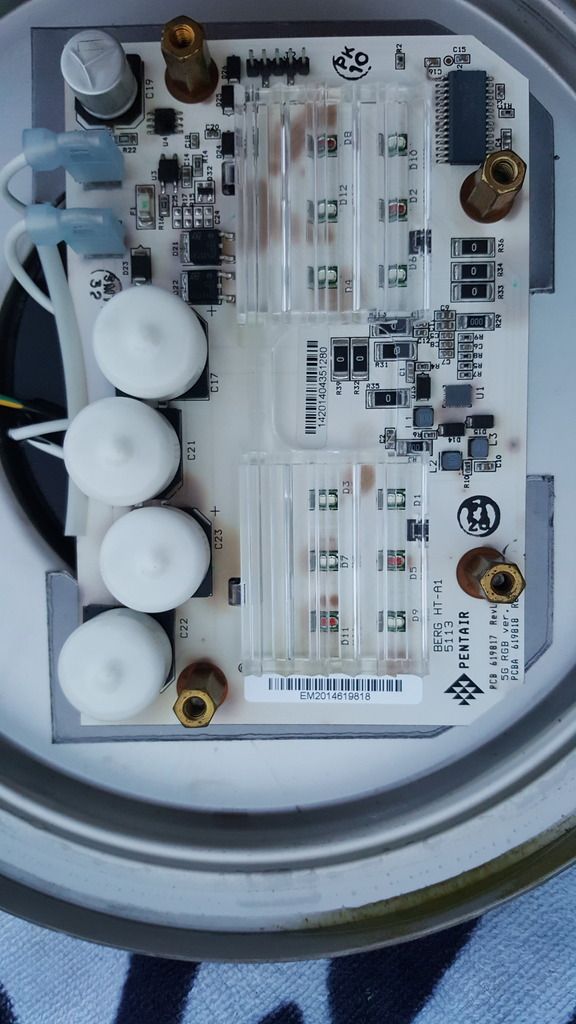
Hello, I'm new to pool ownership and TFP. I'm having the same problem as others with a Pentair LED light. The red has stopped working, but the others still work. I uninstalled the light and can see the board looks charred. My board says it's Rev 2 so I'm not sure this design fixes the problem. What do you all think?


- Nov 12, 2017
- 12,647
- Pool Size
- 12300
- Surface
- Plaster
- Chlorine
- Salt Water Generator
- SWG Type
- Pentair Intellichlor IC-40
Dirk - Just saw your note.
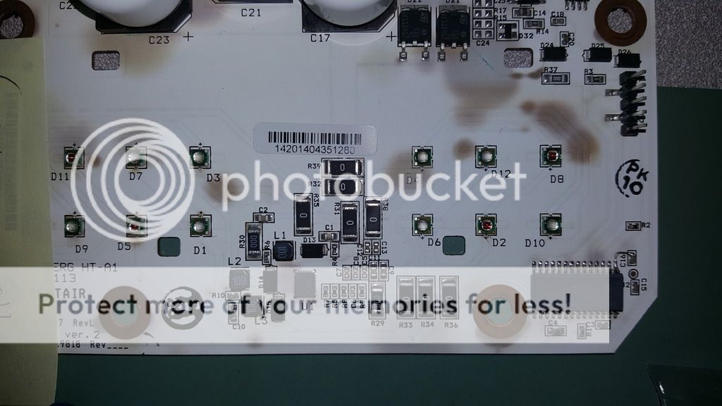
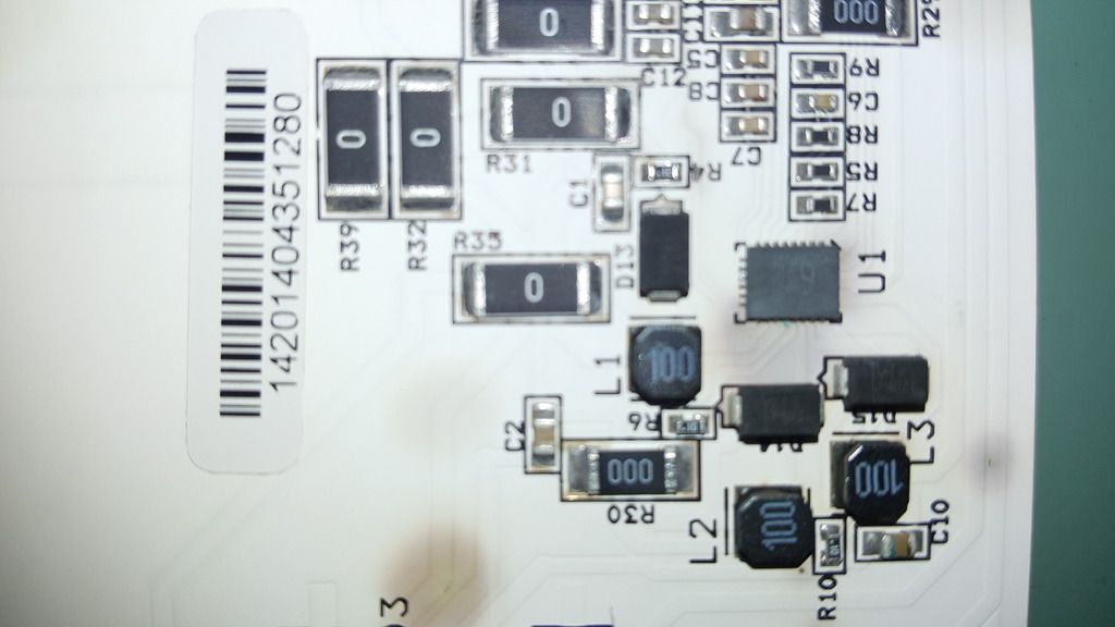
AZ_mb, are the brown splotches on that board what you're saying looks "charred"? If so, it seems like the white copper coating got cooked. I can't quite see the pcb traces in your photos, but looking at my Rev2 board it appears that there are traces where yours has the brown spots.
- Pop off the plastic lens and see if your splotches are on pcb traces, which could suggest an over-heat or over-current event
- Does U1 show any signs of cracking/burning/letting out the magic smoke?
- Do you have a multimeter and a 12vac supply? I'd be curious how much current yours draws... I get 374mA measured on the primary (mains side) of a 12vac transformer and 2.63A measured on the secondary (12 vac side). That may vary depending on what color yours is set to, but I don't think you should see anything wildly different.
Tom
Thanks guys.
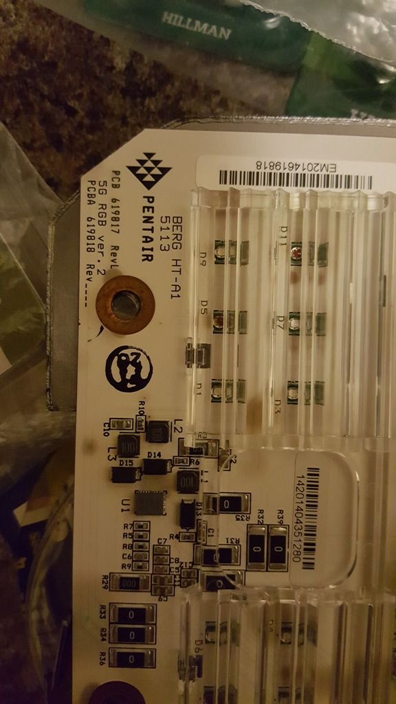
ogdento, yes the brown spots are what I'm saying looks charred. I've taken several additional pics that may help you see what it looks like. Are other failing boards showing different signs than this? I assumed this was overheating as others have reported. A friend of mine spoke to his buddy who runs a pool service company and he said the only problems he's seen with the Intellibrites is when they are wired backward. I don't see any polarity indicators on the board or the wires. Does this makes sense to you? I'll try an get a meter on the board tomorrow and get a reading.
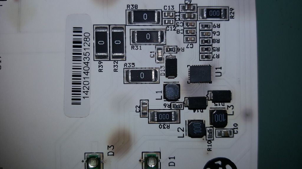
ogdento, yes the brown spots are what I'm saying looks charred. I've taken several additional pics that may help you see what it looks like. Are other failing boards showing different signs than this? I assumed this was overheating as others have reported. A friend of mine spoke to his buddy who runs a pool service company and he said the only problems he's seen with the Intellibrites is when they are wired backward. I don't see any polarity indicators on the board or the wires. Does this makes sense to you? I'll try an get a meter on the board tomorrow and get a reading.


Hey thanks for adding the pictures... that is interesting, I've never seen that... I've only seen boards with a burned up U1 (led driver). Hmm, and it does look like the spots are on the traces.
These boards take 12 volts AC so you can't hook em up backwards... also be sure to set your meter to AC amps, not DC!
These boards take 12 volts AC so you can't hook em up backwards... also be sure to set your meter to AC amps, not DC!
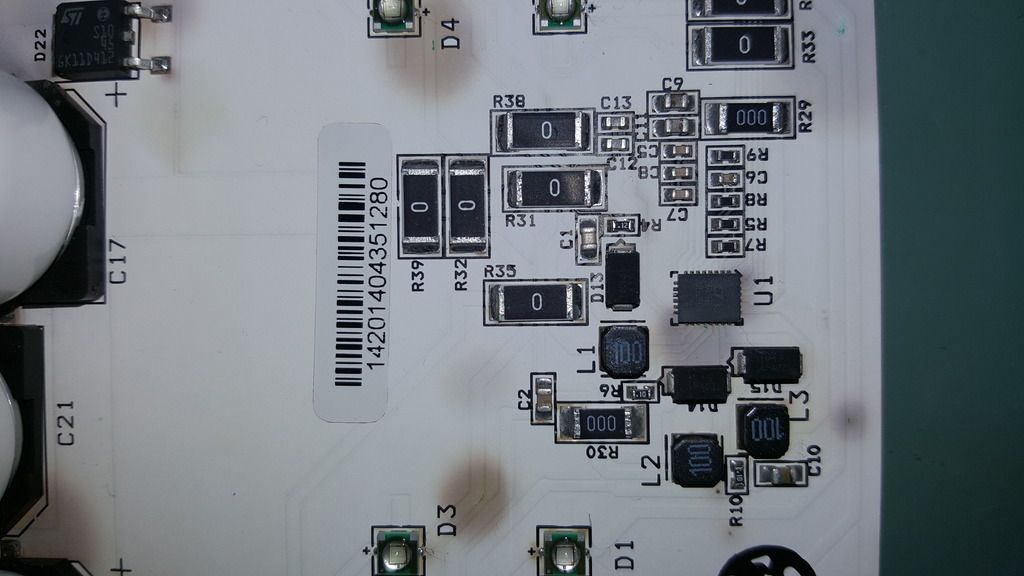
I removed the PCB and the terminals broke off so I'm going to have to try an fix those to recover this board. There is also corrosion on one of the pins on the LED driver. If you look closely you can see the green spot in the pics I posted previously.
Looking closer at the design of this light, the heat is intended to transfer from the copper backing of the PCB to the light housing to the water. Hence the instructions say not to operate out of the water for more than 10 seconds. I think there are two problems with the heat transfer capacity. One, the copper on the PCB is relatively thin and two, it only touches the light housing on the outer sides. The center where the LED driver is has no contact with the housing. This means the heat dissipation capacity is not high enough to keep the board from overheating.
I don't think a heat sink is a good solution for this application because there is no airflow which means the heat sink won't be able to remove heat efficiently once it is warmed to operating temperature. I think what is needed is more efficient heat transfer to the housing which transfers to the water. Basically there needs to be thicker copper touching more of the light housing.
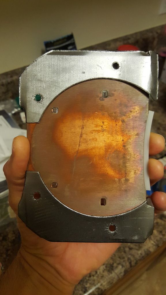
I picked up a sheet of copper remnant from a local metal store and cut it into a ~7" circle. The top was notched out for wiring and some divots were made for the plastic light diffuser that attaches to the PCB. I used some Arctic Silver thermal paste along the light housing to allow for better heat transfer between the copper plate and the housing.
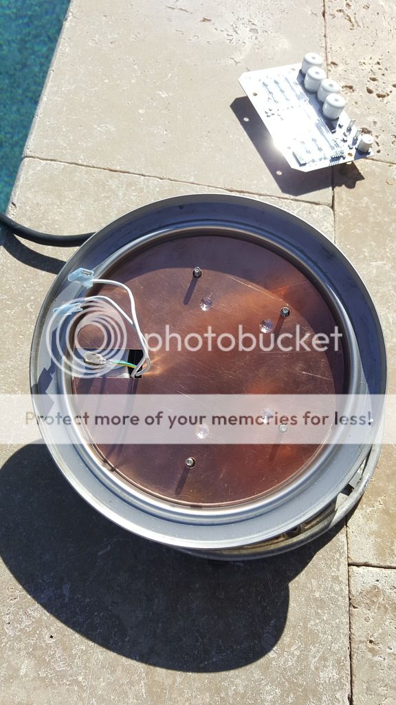
I'm going to try an recover the broken PCB if I can, but I decided to go ahead and get a new PCB because I found one for sale for $150. Seems cheap compared to the $400 if you buy through a Pentair retailer (a complete ripoff for a product that won't last long out of warranty). I then mounted the PCB onto the copper plate and used the thermal paste again between them.
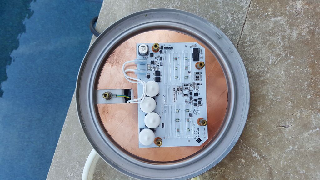
Bolted it all back up with a new seal and so far so good. I wish there was an easy way to measure the temp so I could determine how effective this setup is, but with it having to operate in water I really didn't want to burn up another board running tests out of the water. Time will tell how effective this is. The only other improvement I thought about was conformal coating the PCB. As I mentioned one of the pins on my old board had corrosion so moisture is probably another issue for these lights. If anyone tries conformal coat make sure you mask off the LEDs. They have a rubberized lens that the conformal coat will dissolve.
Looking closer at the design of this light, the heat is intended to transfer from the copper backing of the PCB to the light housing to the water. Hence the instructions say not to operate out of the water for more than 10 seconds. I think there are two problems with the heat transfer capacity. One, the copper on the PCB is relatively thin and two, it only touches the light housing on the outer sides. The center where the LED driver is has no contact with the housing. This means the heat dissipation capacity is not high enough to keep the board from overheating.
I don't think a heat sink is a good solution for this application because there is no airflow which means the heat sink won't be able to remove heat efficiently once it is warmed to operating temperature. I think what is needed is more efficient heat transfer to the housing which transfers to the water. Basically there needs to be thicker copper touching more of the light housing.
I picked up a sheet of copper remnant from a local metal store and cut it into a ~7" circle. The top was notched out for wiring and some divots were made for the plastic light diffuser that attaches to the PCB. I used some Arctic Silver thermal paste along the light housing to allow for better heat transfer between the copper plate and the housing.

I'm going to try an recover the broken PCB if I can, but I decided to go ahead and get a new PCB because I found one for sale for $150. Seems cheap compared to the $400 if you buy through a Pentair retailer (a complete ripoff for a product that won't last long out of warranty). I then mounted the PCB onto the copper plate and used the thermal paste again between them.

Bolted it all back up with a new seal and so far so good. I wish there was an easy way to measure the temp so I could determine how effective this setup is, but with it having to operate in water I really didn't want to burn up another board running tests out of the water. Time will tell how effective this is. The only other improvement I thought about was conformal coating the PCB. As I mentioned one of the pins on my old board had corrosion so moisture is probably another issue for these lights. If anyone tries conformal coat make sure you mask off the LEDs. They have a rubberized lens that the conformal coat will dissolve.
Last edited:
santacruzpool
Gold Supporter
Looks like a good solution - fingers crossed it solves your issues...
(as an aside, that is one huge light - I am used to my little nicheless lights that are only 2-1/2" in diameter)
(as an aside, that is one huge light - I am used to my little nicheless lights that are only 2-1/2" in diameter)
Thread Status
Hello , This thread has been inactive for over 60 days. New postings here are unlikely to be seen or responded to by other members. For better visibility, consider Starting A New Thread.