Thank you for all your help. Do you like the way they look in the pool the same as the pentair lights? Just as bright, light up the whole pool?Yes, you cycle the light on and off 3 times and that resets the lights to the first color in the series. I've had to do this a few times on mine and they haven't had any trouble syncing.

Pentair IntelliBrite 5G Defect
- Thread starter Dirk
- Start date
You are using an out of date browser. It may not display this or other websites correctly.
You should upgrade or use an alternative browser.
You should upgrade or use an alternative browser.
I think they might be a little brighter. It would be nice if they lined up with Pentair automation but they get the job done...Thank you for all your help. Do you like the way they look in the pool the same as the pentair lights? Just as bright, light up the whole pool?
There are a few odd lights shows like green, yellow, orange and a weird red one
Sounds great. Thank you!I think they might be a little brighter. It would be nice if they lined up with Pentair automation but they get the job done...
There are a few odd lights shows like green, yellow, orange and a weird red one
DosDiablos
New member
Hey Guys (and Girls).
Thought i'd throw my "Intellibrite 5G Color" question on this thread because i know there are already a ton of others problem threads so don't want to create more clutter ... and this seems "active" with some very knowledgeable individuals.
+ there is a reference by "bdavis466" to an "Internal Transformer" which is also my secondary question.
So i have an Intellibrite 12v (model #601011 / 619818Z Light Board). I got it cheap because someone/somehow cut the Main Cord down to only about a foot out of the Housing. Figured i'd splice in a new Main Wire and seal it with a couple layers of adhesive shrink wrap and waterproof connectors.
Anyway, i have almost everything working, even the Board/LED Lights ... except no 12v power out of the two White Wires coming out of the black rubber "plug" in the Housing (light is taken apart).
I'm running 110v to the Intellibrite Color Controller, to a Intermatic 12v Transformer, to 12v through Main Cord and i DO get 12volts out to the Light.
Problem is i do not get anything out of the two White Wires ... no continuity or anything.
Sooooo, again, i saw a reference to an Internal Transformer. It seem like there's a problem inside the housing as current seems to stop at that point.
But if i'm getting it right, "bdavis466" said on a 12v Light, there is no Internal Transformer (which i thought might be the problem).
So now i'm stumped.
Do you see anything incorrect, or can give me advice on why there might be no power out of the White Wires although there IS power at the Housing? .. is there a Transformer on a 12v Light?
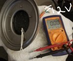
What's in that Black Plug in the Housing if anything ... i'm sticking the two Probes from the Multimeter into the two White Wires out of the Housing and assuming i would see 12v, is that correct testing? .. I am also testing while switching the Color Controller as i believe is send "pulses", but i do not see any 12v pulses.
Thx for any direction
Thought i'd throw my "Intellibrite 5G Color" question on this thread because i know there are already a ton of others problem threads so don't want to create more clutter ... and this seems "active" with some very knowledgeable individuals.
+ there is a reference by "bdavis466" to an "Internal Transformer" which is also my secondary question.
So i have an Intellibrite 12v (model #601011 / 619818Z Light Board). I got it cheap because someone/somehow cut the Main Cord down to only about a foot out of the Housing. Figured i'd splice in a new Main Wire and seal it with a couple layers of adhesive shrink wrap and waterproof connectors.
Anyway, i have almost everything working, even the Board/LED Lights ... except no 12v power out of the two White Wires coming out of the black rubber "plug" in the Housing (light is taken apart).
I'm running 110v to the Intellibrite Color Controller, to a Intermatic 12v Transformer, to 12v through Main Cord and i DO get 12volts out to the Light.
Problem is i do not get anything out of the two White Wires ... no continuity or anything.
Sooooo, again, i saw a reference to an Internal Transformer. It seem like there's a problem inside the housing as current seems to stop at that point.
But if i'm getting it right, "bdavis466" said on a 12v Light, there is no Internal Transformer (which i thought might be the problem).
So now i'm stumped.
Do you see anything incorrect, or can give me advice on why there might be no power out of the White Wires although there IS power at the Housing? .. is there a Transformer on a 12v Light?
What's in that Black Plug in the Housing if anything ... i'm sticking the two Probes from the Multimeter into the two White Wires out of the Housing and assuming i would see 12v, is that correct testing? .. I am also testing while switching the Color Controller as i believe is send "pulses", but i do not see any 12v pulses.
Thx for any direction
The 12v lights don't have the internal transformer which is why you need an external one.
Post some pictures of what you have going.
Post some pictures of what you have going.
DosDiablos
New member
So i have a verified 12volts through the Light's "Main Cord" (12v to white & black wires, green to ground),
However, nothing out the two White Wires to the Board.
If i check Continuity through the Black & White Wires ... there is nothing reading on the two White Wires coming out the "Black Rubber Thing"
Current seems to stop at the Housing ... am i doing something dumb?
However, nothing out the two White Wires to the Board.
If i check Continuity through the Black & White Wires ... there is nothing reading on the two White Wires coming out the "Black Rubber Thing"
Current seems to stop at the Housing ... am i doing something dumb?
Attachments
Last edited:
That should work, I'm not sure why it isn't.
On another note, you shouldn't use that light anyway. I thought you were using the driver from the light that was cut short, not the actual housing.
I wonder if that light mistakenly received 120v at some point and damaged the light.
On another note, you shouldn't use that light anyway. I thought you were using the driver from the light that was cut short, not the actual housing.
I wonder if that light mistakenly received 120v at some point and damaged the light.
DosDiablos
New member
I know the cord is short, figured Adhesive-Waterproof Wire Connectors + two layers of Adhesive Heat-Shrink Wrap should keep the connection waterproof .... + it's 12v so no deaths if it fails.
I'll be honest, we really never use our Pool (especially at night, not heated), it's just for looks/parties.
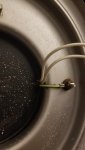
The Driver/Board/LED Bulbs work fine ... i just can't get it past this Black Rubber Thing ... if there is nothing in it, then there is nothing to "blow" ... even if there was an accidental 120v
So what could stop the current at that spot you think?
Anyone know what kind of connection is in there that could cause the current to cease?
I'll be honest, we really never use our Pool (especially at night, not heated), it's just for looks/parties.
The Driver/Board/LED Bulbs work fine ... i just can't get it past this Black Rubber Thing ... if there is nothing in it, then there is nothing to "blow" ... even if there was an accidental 120v
So what could stop the current at that spot you think?
Anyone know what kind of connection is in there that could cause the current to cease?
- Jul 21, 2013
- 65,171
- Pool Size
- 35000
- Surface
- Plaster
- Chlorine
- Salt Water Generator
- SWG Type
- Pentair Intellichlor IC-60
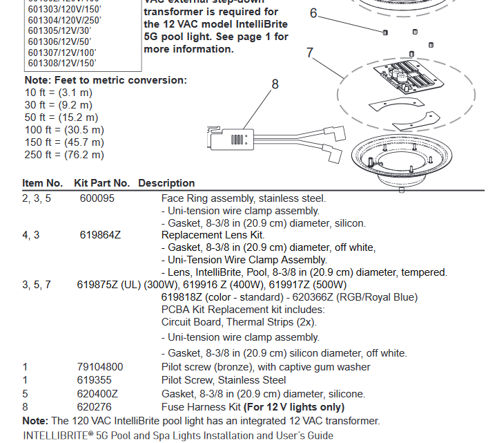
That black plug is a fuse harness. Fuse probably blew and needs to be replaced. See page 20 in https://www.pentair.com/content/dam...lor-pool-spa-lights-manual-english-french.pdf
I have no idea. I don't think I've ever messed with a 12v intellibrite.
The transformers in the 120v lights are sealed in epoxy like that so I'm surprised to see it in a 12v fixture?
The transformers in the 120v lights are sealed in epoxy like that so I'm surprised to see it in a 12v fixture?
DosDiablos
New member
Ya, i don't have a little Fuse Harness/Plug like the one pictured.
My White, Black & Green Main Wires disapear into the Black Rubber, then come out two White Wires (see pic).
Ok, maybe i'll hit up Pentair.
Guess i'm prob screwed as it looks like even if there is something in there, it does not look replaceable (but would still like to know).
Figures my luck ... with all the issues with the Boards, my Board actually works but have an issue in the Rubber Plug Thingy (shaking head) .. LOL!
Attachments
Last edited:
ltmarkm
Member
Hey middy! I think you are wrong on your voltage. Based on your photo above, I believe your 12v transformer is within the molded silicone (or whatever the sealant is) right beneath that board. I have a similar issue right now. If you take a multimeter on 20VAC setting and put the + lead on one of the white wires and the - lead on the other wire, with the light turned on at the control center, I'm pretty sure you will get 12 v if it is good! Mine is only 4.5 volts. I have a new Pentair® 619818Z Kit IntelliBrite® 5G PCBA Pool Aftermarket × 1 (as in your image 0919 above) but won't work because the transformer is bad. I'm having difficulty locating the portion of the light fixture that has the transformer in it! My original light board, like yours had, was fried. Research shows they are expensive and fail far too often.
My suggestion to you is to check the voltage of the fixture where they come out of the sealant and if withing spec, buy the Sunseeker board!
My suggestion to you is to check the voltage of the fixture where they come out of the sealant and if withing spec, buy the Sunseeker board!
Anyone ever have luck when the transformer didnt produce 12v? Similiar to above, mine outputs 6.5-7 volts across the white female tab wires. Replacement board wouldnt work, and was hoping sunseeker may function at lower voltage. Anyone ever dig into the epoxy to look at the transformer?
If not, anyone have tips on pulling the wire thru the conduit? Watched the videos, had an installer come out and he said it was just too tight and he didnt want to break the pvc conduit and make a leak? Does that make sense? It has just the main power wire and the green ground/binding wire thru the same conduit. Doesnt want to budge though with moderate pulling.
If not, anyone have tips on pulling the wire thru the conduit? Watched the videos, had an installer come out and he said it was just too tight and he didnt want to break the pvc conduit and make a leak? Does that make sense? It has just the main power wire and the green ground/binding wire thru the same conduit. Doesnt want to budge though with moderate pulling.
Flying Tivo
TFP Guide
- Jan 24, 2017
- 3,100
- Pool Size
- 7500
- Surface
- Plaster
- Chlorine
- Salt Water Generator
- SWG Type
- Pentair Intellichlor IC-40
I used silicon lube on the cord before installing and it was a breeze. The black epoxy thing on the back serves 2 purposes, to seal out water and to cover the transformer on the 120v units for safety. You could try to dig it out with a heat gun but you will probably melt the wires anyway. You could try to bring it all out of the fixture and convert it to 12V and reseal with epoxy(new long cable). Remember its VAC not VDC.
Well it's been a while since I've been on here. I just came back to post an update. I did the copper plate mod to both lights in the pool and the one in the hot tub. Of the two in the pool, one was a new board I ordered from ebay and the other was one of my existing boards where the red LEDs had already stopped working. If you go back and look at my old pics, the board was pretty charred from heat. A friend who helped repair the attachment post I accidently broke off said the board probably didn't have a lot of life in it still. I'm happy to say that it lasted until April of this year with daily usage. I have the lights turn on each evening and run for about 5 hours so that's over 9,000 hours. Given the boards already poor condition, I think the copper heat sink plate is working well.I guess it has been over a year... let's see if @AZ_MB still has a working intellibrite!
cazz... if your transformer is bad but the board is good, can you install a pool safety transformer "on land" and run new low voltage wires (12vac) to the led housing?
The 2nd light in the pool which has the new board is still working just fine as is the spa light. Hopefully this feedback is helpful. And for those who private messaged me about this, sorry it to years to reply. I never got any email notifications from the forum.
I know I'm resurrecting an old thread here, but I think it's easier having this info all in one place. I'm working on fixing the board that just went out (see my post above) and I have replaced the U1 LED driver. As @peteandvanessa noted in another thread, the diodes around the LED driver go bad once the LED driver goes bad. I'm trying to determine what type of diodes they are so I can replace them too. @ogdento do you have any idea what types of diodes they are?
Hey that's awesome news! I'm not able to look at the board yet... not sure off the top of my head what type they are. You see any markings?

Got a few more pics. It's pretty tough to read them. I don't have a scope so these are from my phone.Hey that's awesome news! I'm not able to look at the board yet... not sure off the top of my head what type they are. You see any markings?


Could be a Littlefuse SP4021, a tvs protection diode... But I'm not sure why they'd have used one there - I'll check out my board on Monday
With a multimeter, does it read like a diode? (A tvs will read open)
With a multimeter, does it read like a diode? (A tvs will read open)
Thread Status
Hello , This thread has been inactive for over 60 days. New postings here are unlikely to be seen or responded to by other members. For better visibility, consider Starting A New Thread.