actually we're forgetting something... we're testing everything "in-circuit" and so far we've really only determined that there's a short at the voltage regulator input/ground pins AND at the rectifier's +/- pins. But there are also 3 filter capacitors on the output of the rectifier, so how do you know which part is the broken one??
It's most likely a dead cap or rectifier, but to be sure you have to remove or isolate each device to test them - otherwise you could get tricked. For example, if there IS a shorted capacitor (which is connected across the input and ground on the regulator as well as the +/- on the rectifier), both the regulator and rectifier would also appear to be shorted when they may actually be ok.
to isolate the parts I'd start with the easiest first... these caps always give me a hard time so I'd de-solder and pry up the + pin of the rectifier (be careful not to pull up the board trace) and see if the short at the voltage regulator goes away. If it does, you can be confident the rectifier is blown but I'd test the +/- pins again anyway. If it doesn't, then it could be the regulator or one of the caps... so maybe I'd pull up the regulator input leg and keep testing

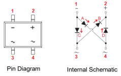
[side note]: I thought it might be worth-while to explain the rectifier testing, so I stole thatoneguy's test results and added some details... I re-labeled the diagram below according to thatoneguy's tests, labeled each internal diode, and added arrows showing the current flow (pos to neg) through the diodes:

+1 to
@Flying Tivo 's point about swapping the lead orientation to help figure out what's wrong. from the above diagram, you'll get current flow with the Red (pos) lead on 1 and Black (neg) lead on 2, but don't expect a tone because the resistance will be above the continuity threshold - my fluke 87 will only beep at ~65 ohms or less whereas the diode resistance will in the megohm range.
You'll get no current flow - aka an open circuit - with Red on 2 and Black on 1... the diagram shows that pin 2 is connected to two cathodes (the line the triangle points to on the symbol), so with Red on 2/Black on 1 the diode is reverse-biased and current is blocked.
for these 4 tests, current should flow through a single diode, and only in one direction:
1&3 = no tone & 684 (with Red on 1, Black on 3... C is forward-biased. you should get nothing if you swap leads)
1&4 = no tone & 688 (with Red on 1, Black on 4... A is forward-biased. you should get nothing if you swap leads)
2&3 = no tone & 671 (with Red on 3, Black on 2... B is forward-biased. you should get nothing if you swap leads)
2&4 = no tone & 680 (with Red on 4, Black on 2... D is forward-biased. you should get nothing if you swap leads)
you shouldn't get anything from 3&4 regardless of the orientation... there's no current path in either direction
Also, with Red on 1 and Black on 2, current will flow through diodes A and D, AND diodes C and B... which gives you a larger voltage drop and higher resistance (the resistance doubles because you have 2 series strings of 2 diodes, and those are in parallel with each other... (A&D in series) in parallel with (C&B in series))


