Pentair Easy Touch Panel 3 amp relays tried to reset them

MahD

Member
Mar 31, 2020
15
Austin, TX
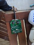
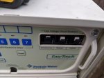
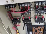
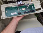
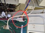
So, I guess I'll start with how this all happened. The pool was working fine this morning, until I went to replace the receiver. I found out it was a bad wire, so I put the old receiver back on it and the pool lights started flickering, and the pumps went haywire. Then I pulled the power breaker and I removed the receiver . After that, the main pump wouldn't turn on, but the waterfall wont turn off. So, I pressed reset and valve and that turned the main pump on and the waterfall was still on. So I tried pulling the power on the whole thing again, now I just had a blank LCD screen. So, I tried to reset the 3 amp relays I pulled the white switch down and the white piece popped out, now I have no screen and no power. I have no idea what to do. I am hoping someone can help me here? I'm lost and I hope the whole thing isn't shot because I replaced a receiver.
 
Last edited by a moderator:
M,

Show us a picture of your EasyTouch's main panel, so we are all on the same page.

Do you have a voltmeter?

When you say you replaced a "receiver", are you talking about a device that talks to a remote inside the house? Or something else.. Show us a pic..

Thanks,

Jim R.
 
Mah,

Welcome to TFP! You've come to the right place for help on this issue.

It really helps a LOT if you can get a photo posted. Jim's an expert on your system and I'm sure he can help you quickly with a photo or if that's not possible please at least describe clearly what you mean by "receiver" and "white switch" and where they are. These are not a terms known to us.

Thanks.

Chris
 
M,

Show us a picture of your EasyTouch's main panel, so we are all on the same page.

Do you have a voltmeter?

When you say you replaced a "receiver", are you talking about a device that talks to a remote inside the house? Or something else.. Show us a pic..

Thanks,

Jim R.
Hi Jim,
Thank you so much for replying. Here is what I replaced, I'm going to post a pictures. This what I was referring to as the receiver. Right below are the 3amp things that won't stay in even with no power going through maybe I am trying to reset them wrong. I am just pushing the white back in. I have 0 power going to the unit and these things still pop back out. I am wondering maybe I am doing it wrong or they are broken. I have also included pictures of the inside. I read another post that said disconnect everything and try to turn it on, I did that and the relays still won't go back in. I do have multimeter.
 

Attachments

  • IMG_20200331_074624.jpg
    IMG_20200331_074624.jpg
    353.6 KB · Views: 29
  • IMG_20200331_080122.jpg
    IMG_20200331_080122.jpg
    205.5 KB · Views: 32
  • IMG_20200331_075729.jpg
    IMG_20200331_075729.jpg
    384 KB · Views: 26
  • IMG_20200331_075712.jpg
    IMG_20200331_075712.jpg
    396.8 KB · Views: 29
M,

Thanks for the pics...

The three little black and white things are circuit breakers.. In theory they should pop open if too much current passes through the circuit. They are wonky, to say the least. It is hard to tell if they are popped or not, as they always have a lot of movement.

With your voltmeter set to DC volts, measure between comport J20 Red and Black.. Measure the voltage with connector installed, right on the little screws.. You should get about 15 to 18 VDC..

If you get zero, then measure the incoming AC voltages at the power connector that is in the upper right of your main board. The voltages are printed right on the card.. 10, 18, and 24 VAC.. You do not measure these voltages to ground. You measure between the two pins that go to each voltage.. If you rotate the card up so that you are looking over the heater connector, into the side of the power connector, you will see where you can measure each set of pins. You should get more than the printed voltages within reason.. About 15, 20, and 25 volts AC..

Please let me know what you find..

Also I need a pic showing the entire box, so I can see all the relays as well as where all the wires go in and out of the main enclosure. Basically, back up a couple of feet.

Thanks,

Jim R.
 
Hi Jim,
Here are the pictures. The picture with red circle that is where you want to me to check the volts right? I don't see the pins you are talking about!
 

Attachments

  • IMG_20200331_112008~2.jpg
    IMG_20200331_112008~2.jpg
    340.8 KB · Views: 19
  • IMG_20200331_111129.jpg
    IMG_20200331_111129.jpg
    653.6 KB · Views: 19
  • IMG_20200331_111126.jpg
    IMG_20200331_111126.jpg
    913.6 KB · Views: 21
A couple of things I want you to do..

Did you test the J20 comport yet or not??

1. Let's make sure that your system transformer is not wired through you GFCI outlet.. Plug something into the outlet and make sure it works.. If not reset the outlet..

2. Let's see if your system transformer has 120 volts AC power.. Use you volt meter and measure between the black and violet wires going up to the transformer which is in the upper right corner of the box.. To do this measure between the red and yellow wire nuts on the upper right side of your box.

3. Here is a shot of the pins on the power connector...


20200331_121136.jpg

Thanks,

Jim R.
 

Enjoying this content?

Support TFP with a donation.

Give Support
Hey Jim,
Thanks for the response. No power on the j20 com port, there is power coming out of the transformer. I think next steps getting replacement relays. I had to hard wire the main pump so pool water still circulates. I talked to tech support, they think I need a new board, but he didn't seem to know about the relays at all which was odd. I wonder if there is a way to bypass those relays just to test? Checked there is no GFCI going to the board only the pool lights
 
M,

That is because they are not relays, they are circuit breakers...

If you have AC power on the power connection pins, then the circuit breakers should be ok..

If you have no power on J20, it could be because you have the wiring screwed up.. Since you were playing with the wires on the other end of this cable that is a good possibility. I suggest that you remove the cable going to J20 and see what happens. Obviously the remote won't work, but it might bring back your display.. If it does, then rewire the cable, making sure the wires go to the right pins.

Another thing to do is remove all relay connections (J8 - J15) and see what happens..

Thanks,

Jim R.
 
Hey Jim,
Things I have tried I disconnected everything but just the transformer and still nothing. I disconnected the j20 nothing. Will the link to that Amazon product work for me Jim? It looks the same I am not sure it will work. Here is the link again . Thanks again for all the help.
 
M,

It looks like it would work to me.. The pic shows a 1/4 amp breaker but the description says 3 amp.

But.. if you measured voltage on the pins I asked you to check, then in theory, the circuit breakers should be ok.

Jim R.
 
With power off @MahD can check for continuity using the multimeter across the circuit breaker contacts to confirm each one is reset.
 
  • Like
Reactions: Jimrahbe
Hey M,
If your breakers are working and you're getting 10/18/24vac out of your transformer, but nothing at J20... one possibility is that you have a short on your board (messing with comm port wires with the board powered up can easily cause this - I've done it myself!). A short makes the board draw too much current, which can pull the J20 red/black supply well below 12-15 volts or even to zero. **The J20 red/black supply comes off the rectified 10vac input, and is what feeds the 5vdc regulator that powers the onboard microcontroller and LCD.

I would disconnect everything from the outdoor board and measure the current draw... assuming your meter has a DC current range, you'll want to run the board off of 12vdc (NOT AC!) and use your multimeter to see how much current it's drawing... it should be under 2-300mA. Start on your highest range!!, 10A probably?, because it might be drawing a lot.

Boards run fine on 12vdc - this is how Pentair powers their trainer boards, but you MUST get the polarity correct... instead of rewriting it all, check this post for instructions on how to power it:

I hope that helps you figure it out!
Tom
 
I hard wired the main pump directly to power temporarily. I ordered 3 new circuit breakers cause they were hosed and a new board(used one from Amazon). I am going to try and replace the breakers first, if I get power to the board after that and everything works cool. I'll just return the board, if the board is bad I'll have to the board to replace it and hopefully everything is working . If both of those don't work I'm not sure the next steps, maybe just replace everything with a raspberry Pi and some relays haha.
 

Enjoying this content?

Support TFP with a donation.

Give Support
Thread Status
Hello , This thread has been inactive for over 60 days. New postings here are unlikely to be seen or responded to by other members. For better visibility, consider Starting A New Thread.