I just checked the pump and yes I have 2 and the label says
MODEL: WFE-12
HORSEPOWER: 3
SERVICE FACTOR: 1.15 (I have no idea what service factor is all about)
I have a rectangular pool about 10,000 gallons. There is also a raised spa.
The main 3hp pump intakes water from the drain and skimmer in the main pool.
The return is through a polaris in floor cleaning system. The pumpkin manifold for this sends the water alternating zones including the spa as one of the zones. The spa spillway returns water to the pool.
The second 3hp pump is for the spa jets.
The pool equipment is pretty far from the pool. I would have to measure and guess (not sure exactly where the pool lines are laid in). Maybe 100' from pool to equipment. Maybe 18" rise from pool surface to pump.
The setup was put in 8-9 years ago and ran like a champ until recently.
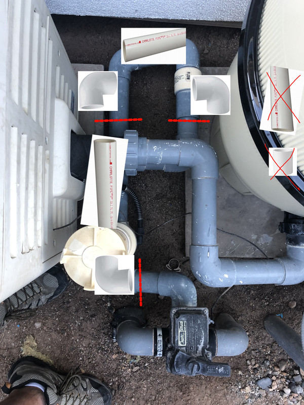
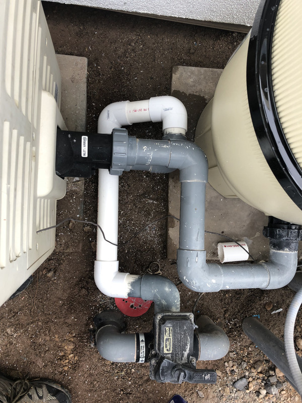
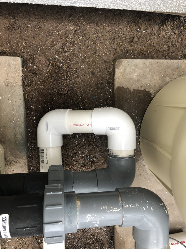
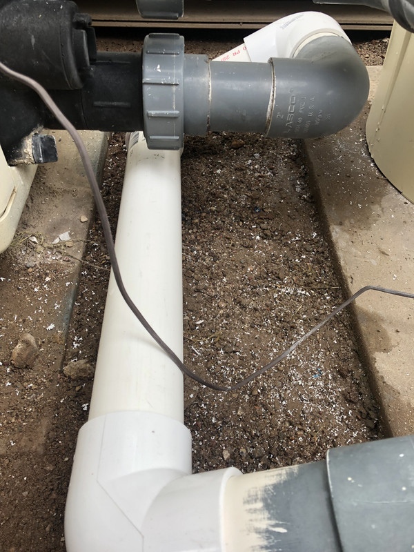
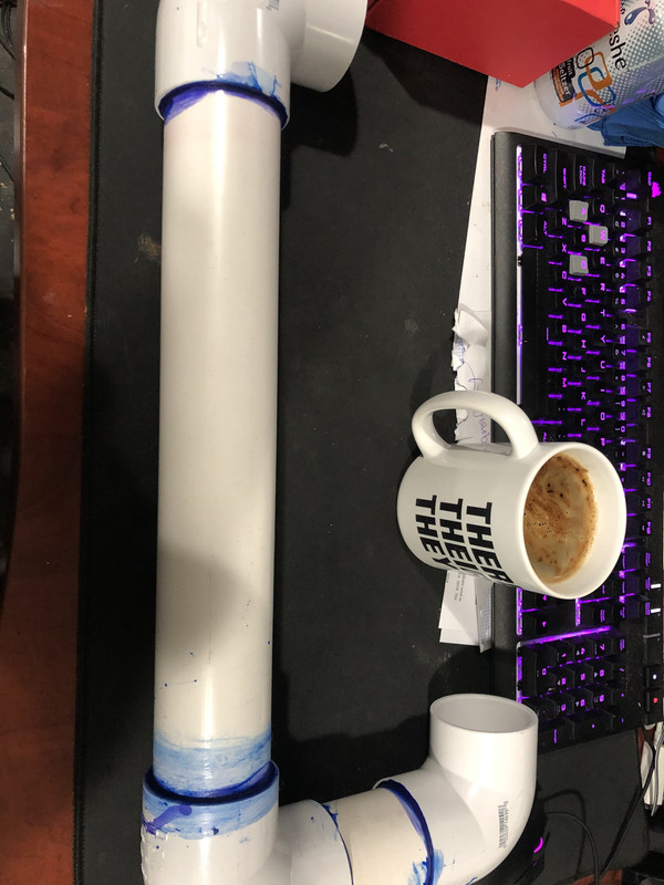
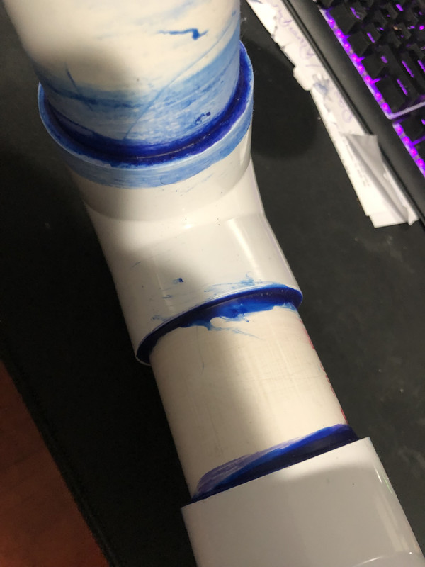
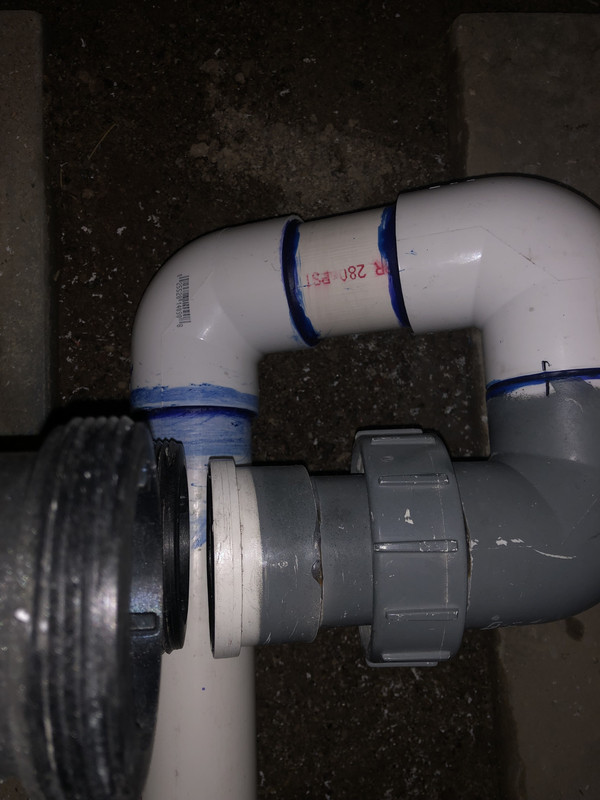
I got the pipe welded up ready to reconnect the bulkhead to the heater as soon as its fully cured. I had to trim the pipe connection flow valve side because of the dry fit issue. I did not realize until long into this that the dry fit would not give a true measurement because the pieces will not fully seat unless lubed up with the glue. It was about 1/4" per connection. So I trimmed the last piece and made it work. There is about 1/4-1/2" space between the bulkhead fitting and the heater. I think that the pipe will give enough flex in that direction to seat the seal. What do you think? Picture attached.
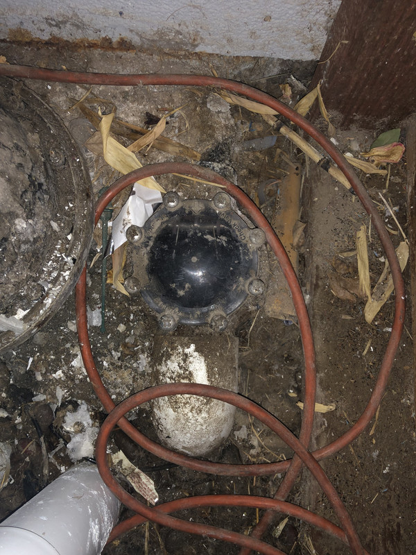
I checked the union at the infloor and there was NO BASKET in the top of the pipe. I have serviced that unit several times since owning and would never leave out the basket. I get a new one with the rebuild. I think the last guy that helped me with the pumps might have gone in there and left it out. I looked in the hole and there is no way that basket could have totally disappeared through the infloor. It is a mess of delicate plastic gears and pins. There would be evidence of it if it went through. I put a spare basket in that I had in a rebuild kit I had on the shelf.
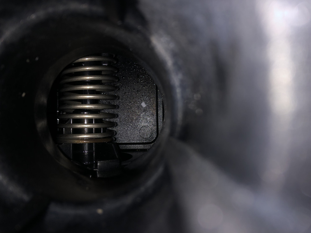
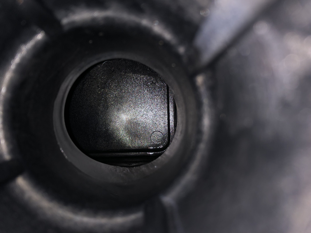
I looked in the heater through the bulkhead holes with my phone and light. I am not sure exactly what I was looking for but I did not see any obvious damage. It looks clean and serene up there to me. Pictures attached.
Once it cures (maybe tomorrow afternoon) I can reconnect everything and see if the filter still leaks and shows the same PSI. If so, I can remove and re seat the filter top and see if that stops the leak. If it all works with the pump, I am not sure its justified to get a new pump. The system has worked for 8 years and the pumps are still chugging away. What would be the next step down 2hp?
One more thing I forgot to mention. It has been going on so long I had forgotten. The spa loses water if the pumps are off. If the pump is off then the spa water level will drop maybe half way to the bottom. The spa is elevated above the pool. I have had a few different companies look at this. Replaced a check valve here, diverter valve there but never actually fixed the problem. This has been a couple years now. But, if I keep the pumps on a regular schedule it keeps the spa full. Could this have something to do with the high PSI? If I want to check the check valves can I just open them up and look inside or are there gaskets that need to be replaced once opened? How about the Jandy diverter valve can I just undo all the screws and lift it up to see inside the valve?
Thanks as always!
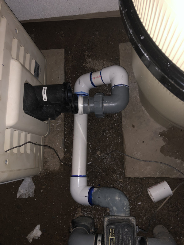
HEATER INLET
HEATER OUTLET
SPACING AT HEATER BULKHEAD
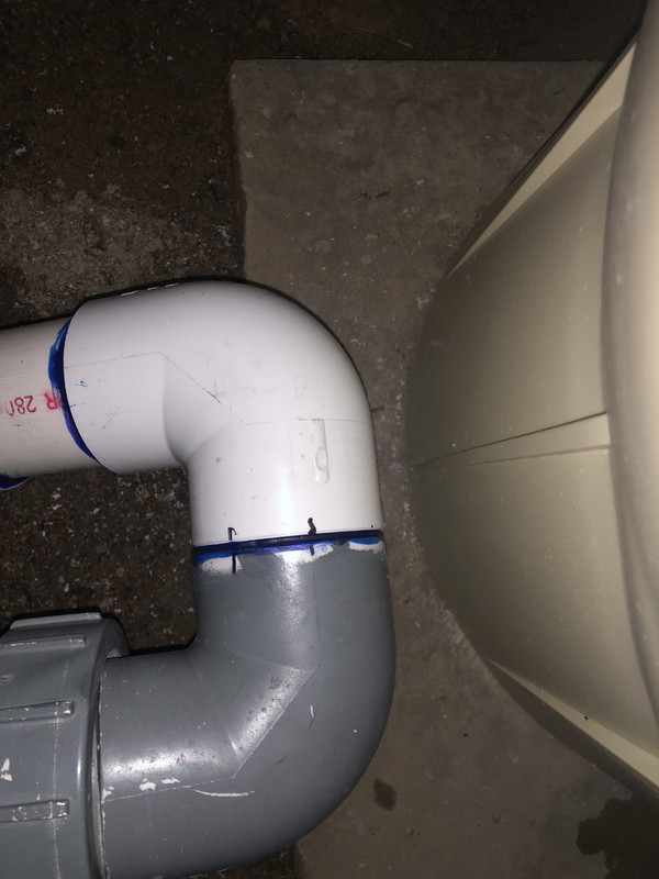
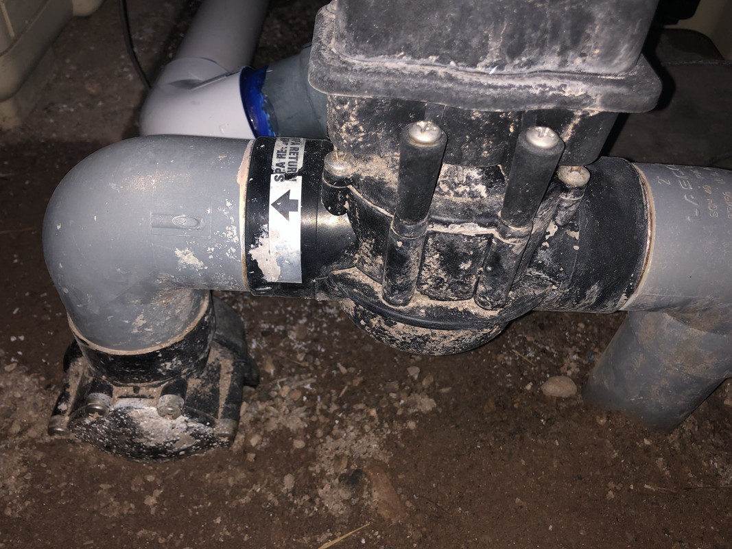
TIGHT COUPLING-IS THIS TOO CLOSE???
THE WHOLE PIPE