May 9, 2016
44
Princeton,NJ
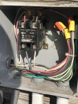
Have a super old and unsafe pool timer. Has a neutral terminal, line terminal and load terminal.

There is a 2 pole 30amp breaker feeding a 40amp 2 pole desperate contactor.
The load side of contactor is connected to the pump.

There is a 120v 15amp feeding the timers neutral and line.

I also have an IC40 installed and they have the hot on the power source terminal of the timer so of course it’s always on.

Anyways I want to replace the timer. Since I really have 2 loads that are 120v what intermatic outdoor timer would work? Anyone using anything that is controlled with an app?
 
Have a super old and unsafe pool timer. Has a neutral terminal, line terminal and load terminal.

What is unsafe about your existing timer?

There is a 2 pole 30amp breaker feeding a 40amp 2 pole desperate contactor.
The load side of contactor is connected to the pump.

What is a "desperate contactor"?

Please post pics of your existing equipment and wiring.

There is a 120v 15amp feeding the timers neutral and line.

So you have separate power feeding the timer then the pump feed?

Intermatic timers usually use the same power for the timer as for the equipment.

I also have an IC40 installed and they have the hot on the power source terminal of the timer so of course it’s always on.

This is incorrect installation. The IC40 Power Center should not be powered when the pump power is off. Read...

IntelliChlor_Cell_Should_Not_be_Powered_When_Pump_is_Off

Anyways I want to replace the timer. Since I really have 2 loads that are 120v what intermatic outdoor timer would work? Anyone using anything that is controlled with an app?

Your two loads are a 120V pump and the 120V Intellichlor Power Center?

Sounds like the T101P should work.

 
What is unsafe about your existing timer?

The terminals and wiring are exposed there’s no shield and the timer clips are broken.


What is a "desperate contactor"?

Please post pics of your existing equipment and wiring.

It’s like a relay, coil draws a magnet to complete the circuit. Coil is powered with 120v.
3FBA342B-DA46-41C4-85D9-A3BCE7DF4C35.jpeg


So you have separate power feeding the timer then the pump feed?

Yes. Pump is fed from 2 pole 30 amp breaker through the contact.

Intermatic timers usually use the same power for the timer as for the equipment.

That’s fine the contact only needs 120 and the IC40 power station is wired for 120. I think whoever installed the salt power center mistakenly put it on the timers power terminal.


This is incorrect installation. The IC40 Power Center should not be powered when the pump power is off. Read...

IntelliChlor_Cell_Should_Not_be_Powered_When_Pump_is_Off

What’s the draw by the power center 3amps?


Your two loads are a 120V pump and the 120V Intellichlor Power Center?

Sounds like the T101P should work.

 
That contactor relay looks like it is switching a 240V circuit. Post a pic of the data plate of your pump.

You have a 120V timer switching the relay in a 240V pump circuit. Which is why they did not connect the 120V Intellichlor to it. Although the Intellichlor power center can be changed to 240V power.

Do you want to replace the contactor relay and CB? If so this will become more complex.
 
That contactor relay looks like it is switching a 240V circuit. Post a pic of the data plate of your pump.

Correct the contactor is switching a 240v circuit the pump is wired for it. All works good. The contactor coil is powered by 120v on terminal 2 of timer. Confirmed that is 120v.

You have a 120V timer switching the relay in a 240V pump circuit. Which is why they did not connect the 120V Intellichlor to it. Although the Intellichlor power center can be changed to 240V power.
Since the timer source power is 120 and load power is 120 I don’t see why they wouldn’t put the power center on the load terminal with the coil.

Do you want to replace the contactor relay and CB? If so this will become more complex.

Nope just timer.
 
So the T101P can take 2 loads on terminal 2?

Yes.

Replace the Paragon timer with the T101P and connect the contactor relay and the SWG hot lines to the LOAD terminal. Tie the neutrals together for the contactor relay and the SWG.
 
Last edited:
Great thanks for clarifying.
Yes.

Replace the Paragon timer with the T104P and connect the contactor relay and the SWG hot lines to the LOAD terminal. Tie the neutrals together for the contactor relay and the SWG.

Do they not make a timer that has 120 source power and can handle 2 120v loads?

The 104P requires 240v as source power.

Current timer is 120v source power.
 

Enjoying this content?

Support TFP with a donation.

Give Support
Number of loads just depends on circuit capacity.

Don't put more than 2 wires under a screw. Put a pigtail under the screw and wirenut the loads to the pigtail.
 
T101 feeds all loads from one CB. T103 you can switch two loads from two different CBs. If you jumper L1 to L3 you make a T103 to be a T101. No electrical difference.
 
  • Like
Reactions: westbrook215
Thread Status
Hello , This thread has been inactive for over 60 days. New postings here are unlikely to be seen or responded to by other members. For better visibility, consider Starting A New Thread.