Our First Pool
- Thread starter Zaffor
- Start date
You are using an out of date browser. It may not display this or other websites correctly.
You should upgrade or use an alternative browser.
You should upgrade or use an alternative browser.
Robtown
Bronze Supporter
- Jul 16, 2020
- 135
- Pool Size
- 18500
- Surface
- Plaster
- Chlorine
- Salt Water Generator
- SWG Type
- Pentair Intellichlor IC-60
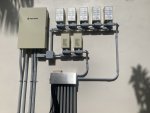
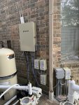
Now that is how things should be wired. I’m loving the configuration of your transformers and the high and low voltage paths with the T junctions on each. I may have to steal that when I redo the poor job our PB’s electrician sub did. I haven’t even taken a picture of the rats nest they left in the load center. I wouldn’t expect them to make a jig like you but at least make some things organized and zip tied.

Robtown
Bronze Supporter
- Jul 16, 2020
- 135
- Pool Size
- 18500
- Surface
- Plaster
- Chlorine
- Salt Water Generator
- SWG Type
- Pentair Intellichlor IC-60
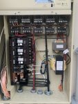
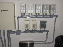
As I’ll be tackling my own wiring project over the next few weeks, let me see if I can decipher your load center...
FLTR relay tied the the top double pole breaker with pump on line and SCG transformer on load
Aux 1, 2, 3, 4 on the top single pole breaker with load running to 4 transformers
Aux 6, 7, 8, 9 on the bottom single pole breaker running the three remains transformers (Aux 9 for future us as no load wire)
Your water feature pump is likely wired directly to the middle double pole 240V breaker.
What is hooked up to the bottom double pole breaker? Looks like Aux 5 with the IntelliCenter Transformer on the line side but what is on the load side, is that future wiring for a heater, maybe a booster pump?
I’d welcome your feedback on my wiring plan in my build thread.
Thanks,
Last edited:
That is how a job SHOULD be done! Time and care taken to keep the rats nests out! Well done!
GOOD EYE!!As I’ll be tackling my own wiring project over the next few weeks, let me see if I can decipher your load center...
FLTR relay tied the the top double pole breaker with pump on line and SCG transformer on load
Aux 1, 2, 3, 4 on the top single pole breaker with load running to 4 transformers
Aux 6, 7, 8, 9 on the bottom single pole breaker running the three remains transformers (Aux 9 for future us as no load wire)
Your water feature pump is likely wired directly to the middle double pole 240V breaker.
What is hooked up to the bottom double pole breaker? Looks like Aux 5 with the IntelliCenter Transformer on the line side but what is on the load side, is that future wiring for a heater, maybe a booster pump?
I’d welcome your feedback on my wiring plan in my build thread.
Thanks,
That last breaker is the 2hp spa blower. The load side powers the blower and the line feeds the relay and continues to the intellicenter just as you saw it.
I wanted to use continuous feeds for the relays as it would eliminate anything coming loose and causing me to lose power to whatever comes after the loose connection. Less points of failure in my mind as well. I thought it would be the beat way to keep the wiring as clean and streamlined as possible. I am by no means an electrician but I took my time and asked alot of questions.
i think you may be able to run some new flex lines and straighten them up a little? One electrician I spoke with said what I did was ridiculous and he would have useda split gutter boxto run flex up into transformers.
a local co-worker used the method I copied and I think it came out great. He has a few more transformers as well. His build is on here too as South Florida build John and Val i think was his username here. Let me see it I can find it.
South Florida - New In-ground Large Build
here is his build. You can see the wiring of his 2 panels with loads of transformers!!
Also big props to MYAZPOOL who was and continues to be VERY VERY helpful. A wonderful member of this community.
im sure there is a way to link to his user ID butI dont know where it is.
here is his build. You can see the wiring of his 2 panels with loads of transformers!!
Also big props to MYAZPOOL who was and continues to be VERY VERY helpful. A wonderful member of this community.
im sure there is a way to link to his user ID butI dont know where it is.
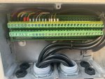
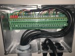
Got through some of my low-voltage / communication wiring today. Most of my runs were too long and needed to be spliced, so I purchased terminal blocks which just barely fit in my low voltage junction boxes and will splice everything on these blocks (two of them).
I was able to run everything through 1” conduit but its a tight fit. I ran 6 cables for intellivalves (24awg 5 conductor) 1 wire for the IC60/Intelliph (16 awg 4 conductor) 3 communication wires for pumps and will use one for future heater (these intelliflo com wires which were actually long enough but I ran through the terminal block anyways) a wire for temp sensor, and 2 cat5 cables.
my thoughts for running everything through termination blocks in addition to extending the cables needed will also allow me to easily replace any cable damaged by sunlight and if I have to replace an intellivalve I just cut the cable to needed length and connect to the corresponding lugs.
wire glands will seal the box where the wires exit.
tomorrow I will make some of the connections in the intellicenter.


RoyR
Bronze Supporter
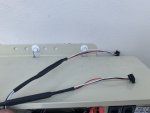
Cut the ends of my intellivalves and soldered them to ends of my wire runs
Made most of my terminations and everything seems to be working fine
i extended the temp sensor, the intellivalves, and spliced the pump communication wires. I wasnt sure these would work but @MyAZPool said he did it and I followed his guidance. Everything works as it should!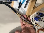
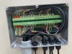
Made most of my terminations and everything seems to be working fine
i extended the temp sensor, the intellivalves, and spliced the pump communication wires. I wasnt sure these would work but @MyAZPool said he did it and I followed his guidance. Everything works as it should!


i should have explained what all that was
I have 2 low voltage junction boxes ran in series all with 1” pvc conduit.
First box has salt cell - heater com - and 2 valves (heater bypass and return valve)
Second box shown in last photo has
2 pump com cables (first 2 pairs)
4 intellivalves (intake and water features)
Temp sensor
Total of 26 wires in this last block which is why I had to split it up (also makes it a bit cleaner)
installed our heater (Pentair Ultratemp)!!!
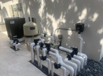
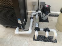
We have been running pump at around 1300 rpm with returns split between pool/spa to keep the spa overflowing smoothly. The pump reports about 20GPM at this speed consuming around 160W. I noticed a drop in GPM when running through heater which I assumed would happen, so I had already planned to automate a bypass. Im still waiting on the intellivalve but it should operate the valve and allow water to run through heater when the intellicenter calls for heat. Cannot verify until its all installed but at least I did get the Pump to increase RPM when heater turns on. Once I know it functions as I hope, I will post my programming steps. As always thanks to @MyAZPool collaborating with me.
I plumbed as much as I could in 2-1/2” pvc reducing at the inlet and outlet of heater. I left a 3/4 tap in case I ever nee


Last edited:
Nice job on the heater! I love seeing the unions!! Those fire bowls, oh those fire bowls!! They are SO pretty!!! I can't wait to see them in action!
Kim
Kim

RoyR
Bronze Supporter
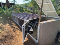
WHOA!!!!Dang, that equipment pad is almost as nice as mine!!!
Link to build pls!!
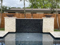
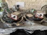
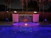
Installed our Fire Bowls yesterday. Had to upgrade the gas line feeding the generator to 3/4” to allow us to feed the bowls from the generator with a 1/2” line. Finished late last night so still have to finish clamping all the conduit and install the mesh and fire glass. Im considering drilling a drain hole on the bottom of the copper bowls to keep water from pooling around the ss wedge anchors that secure the bowls to the wall.

Thread Status
Hello , This thread has been inactive for over 60 days. New postings here are unlikely to be seen or responded to by other members. For better visibility, consider Starting A New Thread.


