Just to be certain, you have checked your filter cycle programming to ensure that your pump is not running from programmed cycles?
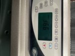
When you say it immediately shows oh and turns on pump, do you mean immediately after the start-up sequence, or immediately when you flip the breaker? Is the spa already overheated when this happens?
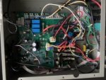
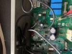
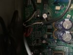
Are your board pics upside down? The gray terminals for pump connections are usually on the bottom.

Bottom of board in pic is a connector, usually gray, that has 3 pairs of wires coming in, the flow switch and both sensors. Remove this by folding the clips on each short side down and away from the connector. Remove this and check for loose wires or corrosion. Use an ohm meter set to 20k ohms to test both sensors. This will be a PITA as the acces in the connector is very limited and awkward to get the test leads on. Also, the location where you will place the leads is the spot where you depress the retaining clip for the wire to remove it from the connector, so they may come out on you. Be sure they make it back in the same spot if they do.
Bottom left corner of pic is blurry in every image. Is there any sign of damage, discoloration, or corrosion there?
Top left of pic there are some white stickers. Next to them is a black relay. Below the relay is a small black square with a silver tab with a screw hole on one side and 3 small tabs on the other. Is there a screw in that screw hole? Is there a nut behind it to screw into? Typically, those components (triac) must be grounded. Not sure if it's related, but worth checking out.
Otherwise the board looks good from what I can see here, which does not at all mean it IS good.
On the bottom right of your pic are the heater relays, with red and black wires on them. With power off, these should all be open (no continuity from one wire terminal to the other on each relay). Check these with an ohm meter to verify your thermostat relay is not sticking and causing the overheat. Be sure power is off while checking.
Disconnect main pump wires from board by depressing the small white tab with a screwdriver or such to open the jaws of the connector. Be gentle or you will break the tab and have a serious problem. With pump disconnected and power off, test for continuity from each pump connector on the board to each of the main power connections (one lead on pump connection, other on main power). These should also be open.
Middle of board is a connector with 2 yellow and 2 blue wires. With power on, check voltage across both blue wires, both yellow wires, and one yellow to one blue. Post results.