No power to heater or pump

If it's not igniting, then it's not a flame sensing issue.

You can verify the voltage and current going to the igniter and you can verify the gas pressure. It's probably going to be one or the other.
 
If it's not igniting, then it's not a flame sensing issue.

You can verify the voltage and current going to the igniter and you can verify the gas pressure. It's probably going to be one or the other.
When you say "going to the igniter" where do I test that?
 
There are two wires going to the igniter.

You can use a clamp ammeter to check the current by clamping around one wire.

Use a good "true RMS" multimeter.

You can also create a set of jumper wires with bare spots to check the voltage.

I would check both at the same time.
 
Not sure if I have a "true rms" multimeter or not. It's digital and I've had it close to 30 years. Definitely don't have a clamp ammeter. Are the wires going to the igniter the ones from s1 and s2?
 
Hope you guys are still with me...

I checked the voltage at the gas valve just now and I'm a bit confused. At ignition, I got 24v from across TR-TH, which is expected. However, after that, it got a little weird.

TR is jumpered over to point #1 and TH is jumpered over to point #2. When the switch is set to off, there's no continuity to 3 and 4. But when I flipped it to on, after jiggling it around a bit, I got continuity from 2 to 4. But here's the weird part - I never got anything from 1 to 3. Worse yet, there was continuity from 3 to 4.

Now, I don't know how this is supposed to work, but a typical relay I would expect would throw from 1->3 and 2->4. If that's the case, this thing is toast.

So, two questions:
1) Am I right about how this is supposed to work?
2) Can I bypass the (assumed faulty) on/off switch and take those spades and put them right on the appropriate TR/TH terminals on the left hand side?
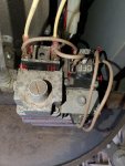
20200509_150958_labelled.jpg
 
I'll be honest - I'm a little afraid to now. Wiggling the switch made things change (aka, it was inconsistent). IIRC, there was 0v reading between 3 and 4 during the last ignition attempt. That's what prompted me to do all the continuity testing, but I didn't try a second ignition cycle after I wiggled that switch. I guess, electrically, if they are both the same, it wouldn't affect anything. I'm pretty cavalier and comfortable around electrical stuff (around it all my life), but adding in that gas makes me a little nervous. :)

In principle though, when the ignition attempts happens, I *should* see 24v across 3 and 4, right?
 
Worse yet, there was continuity from 3 to 4.

If you tested continuity between 3 to 4 with the wires connected then you saw the continuity through the gas valve relay solenoid.
 
If you tested continuity between 3 to 4 with the wires connected then you saw the continuity through the gas valve relay solenoid.
That actually makes perfect sense.

I really feel like this switch on top of the valve is bad and am leaning toward bypassing it altogether. I just want to verify operation of the switch first. I have a manual shutoff about 8 inches from the heater anyway so it's not like I'd ever use that switch.

More investigating to come...
 
And...that was it!! So, for future reference, that on/off switch on top is completely separate from any of the actual valve function. It is a simple double pole, single throw switch that connects terminals 1 and 3 (from my pic) together and terminals 2 and 4 together when switched on. I just took the leads from the solenoid and wired them directly to TH and TR and we have liftoff! Honestly, I think that's the first time that switch has been thrown. Wouldn't surprise me if the closing guys (one of whom was VERY inexperienced) met a little resistance/corrosion and forced it and broke it.

Thanks for all the help guys!!

In summary - my problems were:
1) A loose serial cable on the pump
2) A broken on/off switch on the gas valve inside the heater

Guess who won't be closing my pool again? :) :cautious:
 
  • Like
Reactions: JamesW

Enjoying this content?

Support TFP with a donation.

Give Support
Always tough to figure out when you have multiple problems. It was interesting watching you work through it. I learned about the electrical switch that I did not know was there. I knew there was not a physical gas valve inside.

Great job! :goodjob:
 
  • Like
Reactions: doncaruana
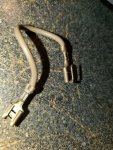
One final note...If anyone is interested in doing what I did, you don't need to pull the wires completely. The jumpers from TR/TH to the switch have a double spade on them to act as an extra terminal (see below). So you can just take the wires from the right of the switch and plug them in to the extra spade from the jumpers by TH/TR (in between the two other sets of wires). So you would have 3 wires over by TR/TH. Or you can just pull the jumpers completely. :)

20200510_211417.jpg
 
Thread Status
Hello , This thread has been inactive for over 60 days. New postings here are unlikely to be seen or responded to by other members. For better visibility, consider Starting A New Thread.