No ground wire to the motor

Aug 18, 2018
49
New Orleans
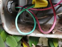
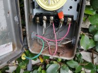
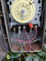
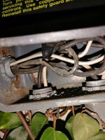
I am about to replace my old motor with a V-Green 1.65 HP Square Flange 48Y Variable Speed Motor, but found that there is no ground (green) wire attached to the old motor. There are only two wires, connected to L1 and L2. Outside of the tube for the wires that goes to the timer, there is another wire that is winding around the tube. It looks that one side goes into the ground, the other end goes to the timer box, but not connected to anything. So, I guess this wire is not used at all. I searched the posts here and it looks that it is not uncommon for very old motors to not have a ground wires, but did not find out solutions. So, must the motor be grounded? If so, how should it be appropriately grounded? Thanks very much!

Wan
 

Attachments

  • wireIntoGround.jpg
    wireIntoGround.jpg
    651.7 KB · Views: 47
  • wireAroundTube.jpg
    wireAroundTube.jpg
    448.7 KB · Views: 48
  • timerBox.jpg
    timerBox.jpg
    319.3 KB · Views: 51
Your current motor is a 110v I assume? Do you have any ground wires coming into the pool timer box or sub panel? All pumps amd wet equipment should not only have a ground amd a bond wire, they should be on gfci protected breakers.
 
Last edited:
What are we looking at in the third pic that shows two red wires and a green wire?
 
What are we looking at in the third pic that shows two red wires and a green wire?
In the third picture, I wanted to show that the end of the wire winding around the tube is connected to anything (see the right bottom corner). I think the two red wires and a green wire go to the salt generator. Do you think the green wire is the ground wire? Thanks.
 
Green wire is the standard color coding for ground wires.
 
I attached two pictures for timer box.

That green wire with a yellow wire nut hanging free looks like a ground wire. Where does the other end of it go to?

Which wires are the hot lines from a CB to feed power to the timer?
 
None of what you have there looks right.

You need to get an electrician to check it out.

It looks very dangerous.

Who replaced the timer mechanism?

Who wired everything?

It looks like you have a hot wire connecting to neutral?
 

Enjoying this content?

Support TFP with a donation.

Give Support
That green wire with a yellow wire nut hanging free looks like a ground wire. Where does the other end of it go to?

Which wires are the hot lines from a CB to feed power to the timer?
Yes, I guess so too. It looks that the other end goes to the timer box of the booster pump, and then to the power supply. I attached a picture for the wiring of the other timer box. Looks the green wire is connected to the naked wire in the picture. Does it sound like ground wire? Thanks very much!
 

Attachments

  • IMG_20210328_194921.jpg
    IMG_20210328_194921.jpg
    414.4 KB · Views: 18
You are giving disjointed views of your old electrical wiring.

You should call an electrician to sort out what you have and bring it up to code.

Lots of things look sketchy and I cannot understand it the way you are presenting it.
 
As others have stated it’s really hard to visualize this complete setup / wiring flow without seeing all the components together or a diagram of how they’re all interconnected.

Green and/or bare should be ground wires. It sounds like someone incorrectly used a blue wire for that small section of ground. If that wire comes out near your pump, that should be your ground wire. But... any electrician worth their salt wouldn’t have added a section of blue to a ground line. So I worry what other corners were cut.

If you’re not 100% certain, as others have mentioned, definitely have it evaluated by an electrician.
 
img_20210328_160604-jpg.318043


In this picture, you can see that a neutral white wire is connected to the first terminal.

When the timer is on, the first terminal connects to the second terminal, which will connect a hot and neutral wire?

Is this thing actually working without tripping the breaker?

You need to get this fixed correctly.

I would shut off the breaker until you can get an electrician to check it out.
Yes, I have it for about 5 years and it always works with no problems. How should the terminals be connected? I found a manual online http://waterheatertimer.org/pdf/Intermatic-T101R201-instruction-manual.pdf. But the diagram has only A, 1, and 2. How are they corresponded with the terminals here (the 5 screws)? Thanks very much!
 

Enjoying this content?

Support TFP with a donation.

Give Support
Thread Status
Hello , This thread has been inactive for over 60 days. New postings here are unlikely to be seen or responded to by other members. For better visibility, consider Starting A New Thread.