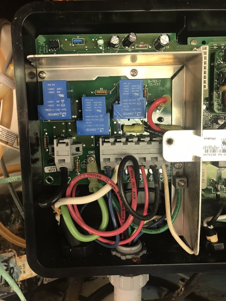
You should have 230v from h1 to H3,
230v from h2 to h4, and
120v from H5 to all the other h terminals
230v from h2 to h4, and
120v from H5 to all the other h terminals

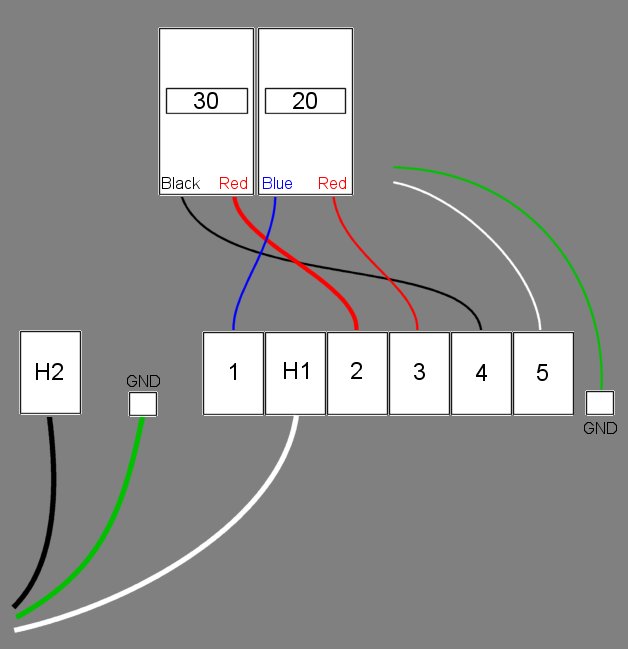
The reason you are not getting anything on h1 and h2 is because you are not supposed to.
If it's wired according to the diagram
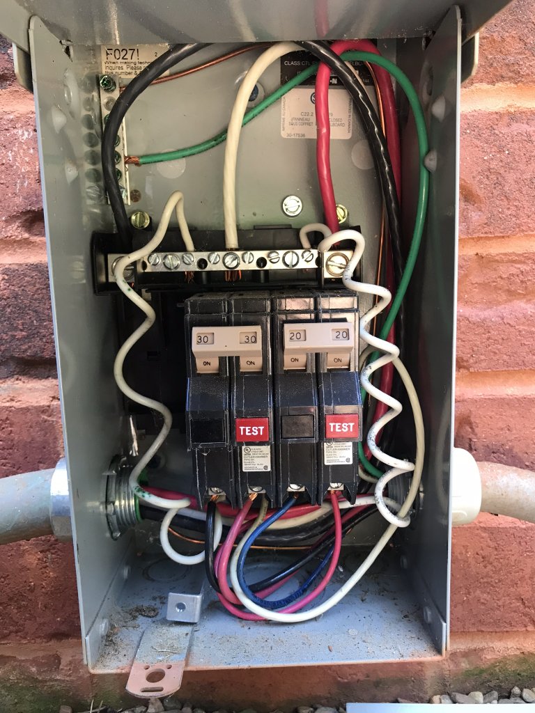
H1 is phase 1 of the 20 amp breaker and h2 is phase 1 of the 30 amp breaker. Put a meter on those and you will get nothing except continuity.
That's correct.
To ground or to H5 you should get 120v


If nobody else has any ideas, I would call tech support. They might be able to tell you if it's a board or controller problem.
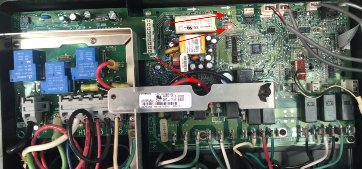
Did you check any/all fuses?
How did you check them?
Checked a few things today.
H1 to H3 gave 114.3v
H2 to H4 gave 114.5v
H5 to all other terminals gave 120v
Circulating pump is running.
Topped off the water
I checked voltages across the bottom of both breakers and got 246v on each breaker.
You should have 230v from h1 to H3,
230v from h2 to h4, and
120v from H5 to all the other h terminals
You should see the 246v you see at the breaker
Please Don't forget to shut the breakers...