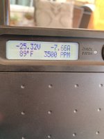
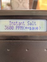
Instant salt is 3500 PPM but the salt reading in Default is 2700 and check system is low salt.
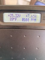
Default is an average, but you are getting a reading of 0000 or 0100 ppm sometimes, which will be included in the rolling average and it will cause the rolling average to be lower than actual.Default is an average right?
For example, if the average is based on the last 5 instant salinity readings and the readings are 3,500 ppm, 3,500 ppm, 3,500 ppm, 3,500 ppm and 0000, then the average is 2,800 ppm.
Some sort of defect in the software or system, but I have never seen it happen like that before.
It will still work as long as the average is at 2,400 ppm, or above, but it will give a low salinity warning at 2,700 ppm.