Need help programming equipment

77,

I would be interested in how it worked before your pool guys swapped boards...

One reason I wanted you to follow the cable back to the automation is to see if you might already have IntelliComm module..

Thanks,

Jim R.
Hey Jim, I did follow the cable but it goes into the big ball of cables, I would have to cut off the zip ties and unravel everything. Afraid of doing that.
 
Goldline introduced AquaLogic in 2003. Hayward acquired Goldline in August of 2004. Hayward discontinued AquaLogic in 2008 and replaced it with Hayward ProLogic. They should have replaced your Aqualogic board with a ProLogic board.

Aqualogic was before the dawn of VS pumps and never directly supported them through their RS-485 digital interface. So we are trying to figure out how your VS pump operated with your Aqualogic board. The ProLogic board can do all the Aqualogic board could do.

The ProLogic board will control a Hayward VS pump. The higher end Hayward OmniLogic board can control a Pentair IntelliFlo pump.
Great info Allen, I am learning tons today, thanks! I guess it was a small miracle that the old board was able to talk to the VS then. So in theory my new boards should talk to my 2013 VP. Right? At least for 2 speeds, which is alright by me. I just don't want it running at a high speed all day long. $$$
 
We are trying to figure out what miracle got your 2013 IntelliFlo VS pump to work with your 2004 Aqualogic system.

It may take you digging into that ball of cables. Get your tool belt ready.
 
  • Haha
Reactions: Janers77
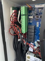
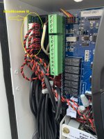
It looks like you have the Intellicomm.

You can set the pump as a two speed pump and that should work for you.

View attachment 362814
That is wonderful news! Now, how do I do that? ;) And what two speeds do you recommend? there are 4 choices 750 - 1500- 2350 - 3110. I did notice today that when the cleaner is running, the VS pump was at 3110.
 
It looks like there are 4 relays already connected to the Intellicomm.

The pump relay and Aux 2 should be connected.

Go into the configuration menu and change the pump type to two speed pump and set aux 2 as pump low speed.

See what other relays are connected to the Intellicomm.


It looks like there are 4 relays already connected to the Intellicomm.

The pump relay and Aux 2 should be connected.

Go into the configuration menu and change the pump type to two speed pump and set aux 2 as pump low speed.

See what other relays are connected to the Intellicomm.


Yipee! Awesome! I will work on this tonight and give it a couple of days to make sure it is running correctly. Do you think this will fix the "check system" error?
 
Do you think this will fix the "check system" error?
Possibly.

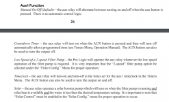
The pump is set as a variable speed pump in the configuration menu.

So, the system is looking for communication from a variable speed pump.

Since it is not receiving the communication, it is giving an error.

Aux 1 might be set as Solar.

I suspect that you can set pump to two speed and that should work.

You can set solar for high speed and low speed for all other operations.
 
  • Love
Reactions: Janers77
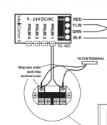
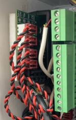
Just to pull this together for you so you understand how the miracle is happening, you have an accessory Pentair Intellicomm board installed in the upper left of your Hayward panel.

The VS pump RS-485 data link cable connects into the bottom of the Intellicomm board. The board then have four connections that relays plug into to control the four speeds of the pump.

When the Aqualogic panel thinks it is closing a relay it actually closing a circuit in the Intellicomm to signal the speed the pump should run at.

This is what makes the magic happen between your Pentair VS pump and the Hayward board. Your installer did not understand what the Intellicomm did for you.

Aqualogic with Intellicomm.jpeg

1628464446660-png.362744


1628464647509-png.362750
 
  • Like
Reactions: Janers77

Enjoying this content?

Support TFP with a donation.

Give Support
Yipee! Awesome! I will work on this tonight and give it a couple of days to make sure it is running correctly. Do you think this will fix the "check system" error?
Welp, I spoke too soon. My Aux 2 is my pool sweep. I have 1-6 Aux.

1 - spa lights
2 - pool sweep
3 - Spa Jets
4 - Waterfall
5 - nothing (as far as I can tell)
6 - nothing (as far as I can tell)

Also, How do I translate the pump speed?
VS pump = Aqua Logic
750 = 25%
1500 = 50%
2350 = 75%
3110 = 100%
 
Just to pull this together for you so you understand how the miracle is happening, you have an accessory Pentair Intellicomm board installed in the upper left of your Hayward panel.

The VS pump RS-485 data link cable connects into the bottom of the Intellicomm board. The board then have four connections that relays plug into to control the four speeds of the pump.

When the Aqualogic panel thinks it is closing a relay it actually closing a circuit in the Intellicomm to signal the speed the pump should run at.

This is what makes the magic happen between your Pentair VS pump and the Hayward board. Your installer did not understand what the Intellicomm did for you.

View attachment 362821

1628464446660-png.362744


1628464647509-png.362750
Thank you so much Allen. I feel like now I can speak "pool talk" and maybe educate them! LOL Super helpful!
 
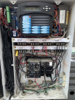
Ok. This gets a little bit complicated.

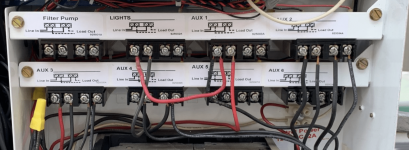
You have a Filter pump relay, a lights relay and 6 aux relays for a total of 8 relays.

I would set the pump as a two speed pump.

The filter pump relay is going to be pump high speed and aux 2 is going to be pump low speed.

Those are the only two relays that I would connect to the Intellicomm.

The lights relay should be for the lights.

Aux 1 should be the booster pump and it should be interlocked to the pump.

Aux 3 can be the jets or fountain.

Aux 4 can be the jets or fountain.

Aux 5 and aux 6 will be unused.

You might need the service personto come back and check the wiring to make sure that it is all correct.
IMG_3150.jpegIMG_3140.jpeg
 
Ok. This gets a little bit complicated.

You have a Filter pump relay, a lights relay and 6 aux relays for a total of 8 relays.

I would set the pump as a two speed pump.

The filter pump relay is going to be pump high speed and aux 2 is going to be pump low speed.

Those are the only two relays that I would connect to the Intellicomm.

The lights relay should be for the lights.

Aux 1 should be the booster pump and it should be interlocked to the pump.

Aux 3 can be the jets or fountain.

Aux 4 can be the jets or fountain.

Aux 5 and aux 6 will be unused.

You might need the service personto come back and check the wiring to make sure that it is all correct.
View attachment 362835View attachment 362836
Ok that makes sense and yes I would need someone to rewire this correctly. I do think the mass amount of extra wire on the left is overkill and needs to be cleaned up, right? That way should there be any further changes it is easy to make simple adjustments.

Thanks again for all your time and help today. This forum is such a value for us newbies! I will be making a gold sponsor donation tomm.
 
  • Like
Reactions: mknauss
Also, How do I translate the pump speed?
VS pump = Aqua Logic
750 = 25%
1500 = 50%
2350 = 75%
3110 = 100%
You don't.

As far as the Aqualogic is concerned, the pump is a 2 speed pump which has high and low.

The filter pump relay will be activated by the Aqualogic for high speed and the Aux 2 relay will be activated for low speed.

The filter pump relay and Aux 2 will be connected to the Intellicomm to one of the 4 programs.

So, let's say that you connect the filter pump relay to program 1 and the aux 2 relay to program 2.

The pump will run program 1 for high speed and program 2 for low speed.

You can program the pump speed to whatever you want for program 1 (high speed) and for program 2 (low speed).

You can use aux 5 or aux 6 to get two additional pump speeds, but the system won't recognize aux 5 or aux 6 as a pump program, so anything that requires the pump to be on will not work unless you leave the pump high speed or pump low speed on at the same time.

For example, the booster pump, SWG and solar all need the pump to be on before they will operate.

Once everything is set up, you can program the timers for pump high speed and pump low speed (Aux 2).

If you only want high speed for solar, you would only set a timer for pump low speed (aux 2) and for solar, set high speed.
 
Last edited:
  • Like
Reactions: Janers77
If you have separate controls for the pool light and spa light, I would put the pool light on the "Lights" relay and the spa lights on Aux 5.

You will need to go back through the configuration menu to assign the Aux relays to the correct function
 
  • Like
Reactions: Janers77
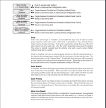
Note: If more than one terminal input is active, the highest input number (GPM/RPM 4) will take priority regardless of the pump setting.

You can use Aux 5 or Aux 6 for an additional speed if you plan it correctly.

As long as the speed is higher than the pump is already running, the pump will go to the higher speed.

For example, if you want the system to run at 1,700 rpm all the time and 2,750 rpm for solar, you can connect aux 6 to program 4 and set set program 4 to 2,750 rpm and aux 6 to "solar".

This will still allow you to have a separate speed for high speed.

So, now you have high speed and low speed and a speed for solar.

High speed can be set for the speed necessary for the gas heater.

There are a few different ways to do what you want depending on the specific requirements.
 
  • Like
Reactions: Janers77
Hi @JamesW,

Hope you had a great week. I have reprogramed my configurations tonight based on your recommendations. I was hoping you can double check them for me. I don't think it worked cause the all the wiring might have to be redone. When I press the original Aux buttons for the spa light and pool cleaner they still work as they originally did.

FYI, before doing these changes, I was getting an Check system: low flow filter off. I suspect this is because it was programmed as a variable speed pump.

Let me know if I have programmed something incorrect.

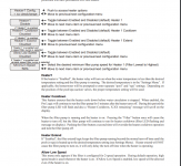
Setting
Spa heater1 - 86 degrees
Pool Heater1 off
Spa Solar off
Pool Solar 87 degrees
Super Chlorinate off
Spa Chlorinator 0% off
Pool Chlorinator 25%
Wireless channel #4


Timers
Filter pump Hi-all
9am to 1pm
Filter pump Lo - all
1pm to 5pm
Spa all off
Cleaner all
10am to noon
Filter pump - all off
Super Chlorinate 1 hours

Diagnostic
Chlorinator off - percentage met
Instant Salt 0000 PPM
Flow switch Flow
Cell temp sensor 88 degrees
Air sensor 97 degrees
Solar sensor 129 degrees
Main software revision 2.93
Display software RFRemote - 08 r4.01
RF Nase Software r3.00 ID: 4993

Configuraton
Chlor. Config. Enabled
Display salt
Cell Type T-Cell-15 (changed to T-Cell-5 for pools up to 20,000 gals

Pool/Spa Config.
Pool/Spa Setup
Pool and Spa - Std (combo)
Spa - counter Manual on/off
Spa spillover disabled
Filter off value, change: enabled

Filter config.
Filter name - Filter pump
Filter pump - 2 speed
Flow monitor - enabled
Freeze protect - enabled
High speed
Freeze temp 33 degrees

Heater1 Config
Heater1 enabled
Heater1 name - Heater1
Heater1 cool down - disabled
Heater1 Extend - disabled
Allow low speed - disabled
Heater2 config

Heater2 disabled

Valve3 Solar Config - enabled

Solar Extend disabled
Solar Priority disabled
Allow Low speed - disabled

Lights config.
Lights name - Lights
Lights function - manual on/off
Light relay standard
Lights interlock - disabled
Lights Freeze - disabled

Aux1 config. was spa lights
Aux2 name - cleaner
Aux2 Function Time clock
Aux2 Relay Standard
Aux2 interlock enabled
Aux2 Freeze disabled

Aux2 config. was pool sweep
Aux2 name - filter pump
Aux2 Function Time clock
Aux2 Relay Standard
Aux2 interlock disabled
Aux2 Freeze disabled

Aux3 config.
Aux3 name - Spa jets
Aux3 manual on/off
Aux3 Relay Standard
Aux3 interlock disabled
Aux3 Freeze enabled

Aux4 config.
Aux4 name - Waterfall
Aux4 manual on/off
Aux4 Relay Standard
Aux4 interlock disabled
Aux4 Freeze enabled

Aux5 spa lights was nothing
Aux 5 name: spa lights
Function manual on/off
Relay standard
Interlock disabled
Freeze disabled

Aux6 nothing
Function manual on/off
Relay standard
Interlock disabled
Freeze disabled

Valve3 config.
Name - Solar valve
Function Solar
Freeze disabled

Valve4 config.
Name Valve4
Aux4 manual on/off
Aux4 interlock disabled
Aux4 Freeze disabled

Remote Menus - enabled
All time clocks - 7-days
Time Format - 12 hours (am/pm)
Units F and PPM
 
First, you have to choose a pump speed for high speed and for low speed.

Let's use Program 1 for high speed and program 2 for low speed.

Go into the IntelliFlo pump menu to set the speed for program 1 to whatever speed you want for high speed and set the speed for program 2 to whatever speed you want for low speed.

Connect the low voltage relay coil wires from the Filter Pump Relay to program 1 as shown in the picture below.

Connect the low voltage relay coil wires from the Aux 2 Relay to program 2 as shown in the picture below.

Go to the Aux 2 configuration and set it to pump low speed.

Go to filter configuration and set it to two speed pump.

Disconnect program 3 and program 4.

If you want a higher speed for solar than pump high speed, connect the low voltage relay coil wires from the Aux 6 Relay to program 3 as shown in the picture below and then set a pump speed for program 3 and set Aux 6 as Solar.
1628910576705.png
1628910633332.png
Keep the lights relay as the pool lights.
Rewire Aux1 to be the booster pump and interlock it to the filter pump.
Aux 3 and Aux 4 can remain as they are.
Rewire Aux 5 to be Spa lights.
1628910702622.png
1628911412130.png
1628911458681.png
1628911580387.png
You will need someone onsite to rewire and program at the same time to make sure that all of the details are correct.

I would run pump low speed 24/7. I would choose a speed for pump low speed that is just enough to make the chlorinator and skimmers work.

The pump should go to high speed for solar or gas heat automatically.

Other than solar or gas heat, there is really no need to run at high speed.
 
Last edited:
Actually, we can probably simplify a little bit with less rewiring.

Leave all Aux relays as they are wired.

Just use the Aux 5 relay as pump low-speed.

Connect the low voltage relay coil wires from the Aux 5 Relay to program 2 as shown in the picture.

Set Aux 5 as pump low speed.

You can use Aux 6 as an additional pump speed if it is higher than pump high speed.

Connect the low voltage relay coil wires from the Aux 6 Relay to program 3 as shown in the picture.

The pump logic will work as long as one of the pump speeds is already on.

If the speed for aux 6 (program 3) is higher than the running pump speed, then it will override the existing speed.

For example, if you want a speed for solar that is higher than pump high speed, just set aux 6 as solar and it will activate when the solar is activated.

You can probably get another speed for gas heater if you want.

That would give you 4 speeds. Pump high-speed, pump low-speed, solar and gas heater.

To get a speed for gas heat, you can probably pick up the voltage on the load side of the low voltage "two-wire" remote relay fireman's switch for the heater.

You would connect that and a ground to program 4.

When the system activates the gas heater, the low voltage from the heater will activate the program 4 pump speed.
 
Last edited:

Enjoying this content?

Support TFP with a donation.

Give Support
Thread Status
Hello , This thread has been inactive for over 60 days. New postings here are unlikely to be seen or responded to by other members. For better visibility, consider Starting A New Thread.