Ironic

Gold Supporter
Oct 9, 2020
14
Middle TN
Pool Size
20000
Surface
Vinyl
Chlorine
Salt Water Generator
SWG Type
Astral VX 11S
I’ve been reading and following TFP articles and members for over 2 years now. This has helped tremendously in understanding terminology, engineering, and best practices in pool construction. However, I am now smack dab in the middle of construction and in a bit of a hard spot…

The original sales person we designed our pool and signed our contract with is no longer an employee for our PB. Here’s why that’s now an issue:

1.) He told us things like “Oh they will only pipe your pool with 2” pipes with the size of this pool and water features you are wanting” when we said we wanted the pool piped with 2” minimum. Because he said this, I didn’t know this was something that even needed to be written out in a contract.
IT IS NOW PIPED WITH 2” SUCTION (skimmers, drain), SLIDE STUB (which is supposed to be 1.5” per manual), AND STUB FOR FUTURE WATERFALL. AND 1.5” FOR x4 RETURNS AND 2 BUBBLERS. DOES THIS SEEM SUFFICIENT FOR WATER FLOW AND TURNOVER? HERE’S WHAT WE HAVE:

•25k gallon 41’x27’x18’ Freeform.
•1.5 HP Jacuzzi/Carvin VS pump
•425 sq ft cartridge filter
•SWG
•Turbo twister slide (25-40 GPM)
•2 bubblers (?GPM - basically just two 1.5” stub-ups at the moment)
•waterfall will be 3’ high with recommended 40 GPM.
•Approx. 40’ straight pipe run from pad to 1st 45°. Then, approx. 15’ straight pipe run to 1st 90°s. Then, it’s 45°s and 90°s in various places over 40’ around pool perimeter.


2.) He informed us that everything would be automated where we could control the pump, lights, everything all in an app.
NOTHING IS THE SAME BRAND, SO THIS WON’T BE POSSIBLE, RIGHT?

I made a crucial mistake thinking this company would use best practices at the pad, as well.

I am not satisfied with any of the plumbing and need help explaining what and why to the PB to get this corrected before any backfill is done. PLEASE HELP ME FIGURE OUT WHAT IS REASONABLE TO ASK FOR/CORRECT, AT THIS POINT, TO OPTIMIZE PUMP/EQUIPMENT EFFICIENCY AND DECREASE THE LIABILITY OF POTENTIAL LEAKS.

We are willing, as homeowners, to rerun all the plumbing ourselves. My husband is knowledgeable in flow and engineering.


Any help is greatly appreciated!

28FE76DF-DACF-4BA1-B406-2FD8CB132ABD.jpeg11A7D036-E51F-42D6-B17A-C63B6D3A70CB.jpeg1BE4E542-E210-4065-A92C-B890B233BCE8.jpeg818E5FB5-0D82-4E8A-91D5-8BB825B35E5E.jpeg646379B6-41D1-48A1-88E1-8D232ED4BBE6.jpeg34C5CC60-004D-47FB-B527-DD57587895E6.jpegC9750D86-9EF1-449F-9617-199711CE7993.jpeg44737E0C-42C7-4973-B9CF-17D6B426E4FC.jpeg0B991521-E8AA-4ED5-8C21-0E95E461AC74.jpeg1B1FDA3C-4E8B-46BF-9F24-597EB951897B.jpeg
 
Last edited by a moderator:
What automation system was planned?

The ball valves used cannot be automated. Diverter valves should have been used instead of ball valves. Ball valves will eventually stick and handles break and need replacement in a few years.

What valves do you want automated?

The things that are crooked are cosmetic and don’t affect the operation of your pool. It is sloppy work and you can discuss correcting it with your builder.

The bubblers not being lined up should have been caught before gunite. Not much can be done now.
 
DOES THIS SEEM SUFFICIENT FOR WATER FLOW
Likely. You have more suction and return than the pump can handle. Besides, you can't move more water than this single pipe can handle, which is far more than the 1.5 HP pump is capable of.

Screenshot_20230302_164428_Chrome.jpg


For comparison, I have a 3HP pump and a single 2 inch return pipe (80 ft long?) that 'Ts' to two returns at the far pool wall.
 
What automation system was planned?

The ball valves used cannot be automated. Diverter valves should have been used instead of ball valves. Ball valves will eventually stick and handles break and need replacement in a few years.

What valves do you want automated?

The things that are crooked are cosmetic and don’t affect the operation of your pool. It is sloppy work and you can discuss correcting it with your builder.

The bubblers not being lined up should have been caught before gunite. Not much can be done now.
We weren’t told what automation system would be used, just that we’d be able to monitor and control the pump and lights via Wi-Fi to set schedules and possibly do “if this, then that” programming.

I made a poor assumption that they wouldn’t use ball valves (because another builder we received a quote from told me “no one does that anymore”). So, that tear down is going to be on us.

I’ll be honest, I didn’t know the valves could even be automated…?

It IS sloppy, and irritating. There are so many unnecessary bends and fittings, which just gives us more possibilities for leaks.

We know we’re stuck with the bubblers being off like that. They piped them and poured the concrete over them all in one day. It was a rather unpleasant surprise when we got home from work.
 
Likely. You have more suction and return than the pump can handle. Besides, you can't move more water than this single pipe can handle, which is far more than the 1.5 HP pump is capable of.
Do you think the pump is undersized? When we brought that up as a concern, we were told it could handle all of the water features and flow. But I’m having trust issues at this point…
 
Diverter valves are automated by putting a motorized actuator on top of it controlled by an automation panel.

What does your written contract say about automation?
 
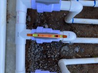
Two of the three suction lines appear to have bushings that reduce the pipe size to 1.5". Can you confirm?

It looks like the center pipe might be the MD because there is a vacuum break on the line? If so, then that means the skimmer is on a 1.5" line which is not a good idea.

What is the other suction line for?


As for flow rate, the bubblers usually around 30-40 GPM. You basically have 4 features at 40 GPM each or a total of 160 GPM. That pump or any other pump is not going to deliver that much flow rate on that plumbing.
 

Enjoying this content?

Support TFP with a donation.

Give Support
Two of the three suction lines appear to have bushings that reduce the pipe size to 1.5". Can you confirm?

It looks like the center pipe might be the MD because there is a vacuum break on the line? If so, then that means the skimmer is on a 1.5" line which is not a good idea.

What is the other suction line for?


As for flow rate, the bubblers usually around 30-40 GPM. You basically have 4 features at 40 GPM each or a total of 160 GPM. That pump or any other pump is not going to deliver that much flow rate on that plumbing.
That is correct, those pipes are reduced down. Why would they do that?
Two skimmers on 1.5” and MD in the middle.

I really appreciate the knowledge and input from you guys. I feel foolish for how blind sighted we’ve been.
 
They really should have used at least 2" for both skimmers since it really doesn't cost that much more. But you can probably live with the setup as you have it now since there are two skimmers. But with 1.5" suction lines, you really should not exceed 38 GPM on each line which is sufficient for just skimming. Combined with the MD, the most flow rate that you can safely support is 140 GPM with all lines operational. However, the pump can't handle that much.

So the design is really not sufficient for all of your water features.
 
Thank you guys for your input. We met with our Project Manager and Construction Manager yesterday.
I spent 2 hours measuring, counting, and converting to get our feet of head. And it’s a whopping 47.57! The PB wasn’t impressed. Not everyone appreciates how much time and math it requires to figure out flow resistance lol.

Our water features alone are completely off the curves for any pump under 3HP with that much resistance.

PB wasn’t willing to rework plumbing to decrease feet of head (we estimated we could drop approx. 16 feet of head with just a better layout). Not surprising. So, now we’re fighting for a larger 3HP pump install.
 

Attachments

  • 57B7164B-CAE6-4B64-B864-EA63DEA53F14.jpeg
    57B7164B-CAE6-4B64-B864-EA63DEA53F14.jpeg
    374.5 KB · Views: 25
  • 9E2F5935-3550-40F1-86C6-4D758D7CE98C.jpeg
    9E2F5935-3550-40F1-86C6-4D758D7CE98C.jpeg
    383.7 KB · Views: 23
  • 6208DEF8-93B5-490F-894A-8B81D8EED0F6.jpeg
    6208DEF8-93B5-490F-894A-8B81D8EED0F6.jpeg
    136.4 KB · Views: 22
  • Sad
  • Like
Reactions: Newdude and kimkats
Thank you guys for your input. We met with our Project Manager and Construction Manager yesterday.
I spent 2 hours measuring, counting, and converting to get our feet of head. And it’s a whopping 47.57! The PB wasn’t impressed. Not everyone appreciates how much time and math it requires to figure out flow resistance lol.
Exactly how did you calculate head loss? It is not a trivial exercise and depends on flow rate through the plumbing which it turn depends on the pump put on the plumbing. Two equations and two unknowns to solve for.
 
Last edited:
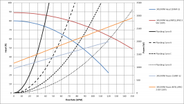
I ran some numbers based upon your description and with all the lines fully open, the operating point is predicted to be at 100 GPM @ 40' of head. The plumbing curve is close to that of Curve D in this plot:

1678480295442.png
 
Exactly how did you calculate head loss? It is not a trivial exercise and depends on flow rate through the plumbing which it turn depends on the pump put on the plumbing. Two equations and two unknowns to solve for.

Did I do this wrong? Please tell me no 😅

C8E25CE2-5416-4486-8E34-FB8DCAE604DF.jpeg
 
Last edited by a moderator:
It is fine to use equivalent length of pipe when estimating head loss in the pipe and fittings but this is NOT the same as head loss. It just gets you one step closer. You then need to calculate the head loss at a specific flow rate BUT that too is not really correct because you need to find the crossover between the pump's head curve and the plumbing head curve. My first estimate for your plumbing head curve is:

Head (ft) = 0.004 * GPM^2

Note that this has a head loss of 40' at 100 GPM but if you use your 150 GPM goal, the head loss becomes 90' of head. Double what you calculated. This of course is not on the Intelliflo's head curve as I showed above. This is why you must use a plumbing curve to determine the actual operating point.

If you plot the plumbing curve over the pump's head curve, where they cross is the operation point which I showed in my previous post. But I did not have your fitting count so it may be slightly off.

I am having a hard time figuring out what you exactly what you did to see where you went wrong. What was your total equivalent length of pipe and what was the GPM that used to determine head loss?

How did you treat the parallel pipe vs the series pipe? Head loss adds with pipe in series. However, when pipe is in parallel, it is much more complicated. The head loss in each pipe must be the same because they share the same input and the same output node. Also, the total flow rate splits into the separate pipes so the resulting head loss is less than if a single pipe carries all of the flow.

Also, a swimming pool "rise" only occurs for water falls and slides. The rest of the plumbing has no rise as it is canceled out by an equal fall.

Also, everything that touches the water adds head loss so skimmers, MDs, eyeballs, exit pipe etc. I don't see these in your calculations.

As I said before, this is not a trivial calculation.

If I get some time, I will update my calculation with your fitting counts.
 
  • Like
Reactions: Newdude

Enjoying this content?

Support TFP with a donation.

Give Support
Thread Status
Hello , This thread has been inactive for over 60 days. New postings here are unlikely to be seen or responded to by other members. For better visibility, consider Starting A New Thread.