
Earlier this year I bought a Black & Decker 3HP VSP on poolpartstogo.com and have just finished its integration with the pool.

The pump is quiet and energy efficient. Here are some numbers:
2400 RPM (priming only) - 2.85A, 683W
2000 RMP (cleaning and/or intensive skimming) - 1.74A, 420W
1600 RPM (normal speed for chlorinating, 80% of running time) - 1.03A, 247W
Compare these numbers to my previous single-speed Jandy PHPM1.0, running always at 3450 RPM and consuming 1600 watts! When B+D is not running, its VSD drive draws 145mA, which is about 35W.
The controller is pretty simple. It runs node-red flows on Raspberry Pi with two Sequent Microsystems HATs: Building Automation and Eight Relays. High-power devices (Circupool RJ-60 SWCG and Polaris PB4-60 pump) are switched with Omron G7 relays installed in a separate relay box. Low-power contacts, such as for controlling B+D pump, are switched directly by the Eight Relays HAT.

An important part of the controller is the current transducer Senva C-2344. I have set it to 30A range and wired inside the electrical subpanel with 3 wraps of one of the lines off 20A 2-pole GFCI breaker feeding the B+D pump, so the transducer converts 0 - 10A current to 0 - 10V voltage, which is passed to one of 0 - 10V inputs (analog to digital converters) of the Building Automation HAT.
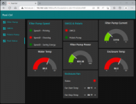
The transducer is pretty precise, with the output very close to the one derived from the B+D display by dividing power by 240V (or whatever voltage one has between the two lines") ). The output from the transducer is used by the node-red flows to provide a safety mechanism preventing SWCG and Polaris booster pump from running when B+D pump is not running at appropriate speed. Here is a screenshot of the dashboard's Pool Status panel (the water temperature 10k sensor is not inserted into the pipe yet, it shows the air temperature):
). The output from the transducer is used by the node-red flows to provide a safety mechanism preventing SWCG and Polaris booster pump from running when B+D pump is not running at appropriate speed. Here is a screenshot of the dashboard's Pool Status panel (the water temperature 10k sensor is not inserted into the pipe yet, it shows the air temperature):

Now a couple of notes on the B+D automation panel. The original panel is swapped with the automation one, which allows for 1) BAU programming of speeds 2) remote selection of one of the three preset speeds. The programming of speeds is easy: set mode to manual, press speed1 button and set it to a desired value, press speed2 and set the value, and so on. The speeds programmed this way are remembered after power disconnect. The speeds can be modified when the panel is in manual mode, but only if the pump is not currently running. (BTW, the manual mode is the only valid mode with the automation panel.)
One more thing, which is not mentioned in the automation manual.

The priorities of inputs in the above diagram, from the highest to the lowest, are: IN1, IN2, IN3. This allows for multiple speeds to be scheduled at the same time, the highest priority input being effectively selected. To lower the number of entries in the schedule, we can superimpose higher priority speeds on top of the lower ones, like in the schedule below:

Controller features:
[EDITED 9/30/2023]
A link to this project's public repository on github:
[GitHub - hexabc/pool-ctrl: Raspberry Pi / node-red based pool controller]
The pump is quiet and energy efficient. Here are some numbers:
2400 RPM (priming only) - 2.85A, 683W
2000 RMP (cleaning and/or intensive skimming) - 1.74A, 420W
1600 RPM (normal speed for chlorinating, 80% of running time) - 1.03A, 247W
Compare these numbers to my previous single-speed Jandy PHPM1.0, running always at 3450 RPM and consuming 1600 watts! When B+D is not running, its VSD drive draws 145mA, which is about 35W.
The controller is pretty simple. It runs node-red flows on Raspberry Pi with two Sequent Microsystems HATs: Building Automation and Eight Relays. High-power devices (Circupool RJ-60 SWCG and Polaris PB4-60 pump) are switched with Omron G7 relays installed in a separate relay box. Low-power contacts, such as for controlling B+D pump, are switched directly by the Eight Relays HAT.
An important part of the controller is the current transducer Senva C-2344. I have set it to 30A range and wired inside the electrical subpanel with 3 wraps of one of the lines off 20A 2-pole GFCI breaker feeding the B+D pump, so the transducer converts 0 - 10A current to 0 - 10V voltage, which is passed to one of 0 - 10V inputs (analog to digital converters) of the Building Automation HAT.
The transducer is pretty precise, with the output very close to the one derived from the B+D display by dividing power by 240V (or whatever voltage one has between the two lines
). The output from the transducer is used by the node-red flows to provide a safety mechanism preventing SWCG and Polaris booster pump from running when B+D pump is not running at appropriate speed. Here is a screenshot of the dashboard's Pool Status panel (the water temperature 10k sensor is not inserted into the pipe yet, it shows the air temperature):Now a couple of notes on the B+D automation panel. The original panel is swapped with the automation one, which allows for 1) BAU programming of speeds 2) remote selection of one of the three preset speeds. The programming of speeds is easy: set mode to manual, press speed1 button and set it to a desired value, press speed2 and set the value, and so on. The speeds programmed this way are remembered after power disconnect. The speeds can be modified when the panel is in manual mode, but only if the pump is not currently running. (BTW, the manual mode is the only valid mode with the automation panel.)
One more thing, which is not mentioned in the automation manual.
The priorities of inputs in the above diagram, from the highest to the lowest, are: IN1, IN2, IN3. This allows for multiple speeds to be scheduled at the same time, the highest priority input being effectively selected. To lower the number of entries in the schedule, we can superimpose higher priority speeds on top of the lower ones, like in the schedule below:
Controller features:
[EDITED 9/30/2023]
- VSP scheduling at three preconfigured speeds, with one-click schedule disabling/enabling:
- priming (Speed1 = 2200 rpm)
- cleaning (Speed2 = 1800 rpm)
- chlorinating (Speed3 = 1600 rpm)
- SWCG scheduling, with one-click schedule disabling/enabling.
- Polaris pump scheduling, with one-click schedule disabling/enabling.
- Allowing the user to manually start/stop the VSP (for any of the preconfigured speeds), Polaris pump and SWCG.
- Monitoring the VSP speed with a current transducer.
- Preventing the user and the scheduler from starting the Polaris pump when the VSP current transducer doesn't report Speed2.
- Automatic stopping of the Polaris pump if the VSP current transducer stops reporting Speed2.
- Preventing the user and the scheduler from starting SWCG if the VSP current transducer doesn't report any speed (reports just a 140mA standby current).
- Automatic stopping of SWCG when the VSP current transducer stops reporting any speed (reports just a 140mA standby current).
- Measuring pool water temperature.
- Measuring enclosure temperature.
- On-off controlling, with temperature hysteresis, of the enclosure fan.
- Charting temperatures of water, controller enclosure and Raspberry Pi CPU for the last 12 hours.
- Sending an email alarm when the VSP current exceeds expected values, indicating, for example, an obstruction in water flow.
- Sending an email alarm when the VSP current is close to 0, which may indicate a tripped circuit breaker.
- Sending "alarm cleared" email when the VSP current returns to normal levels.
- Secure, password protected and TLS-encrypted Internet-wide UI.
A link to this project's public repository on github:
[GitHub - hexabc/pool-ctrl: Raspberry Pi / node-red based pool controller]
Attachments
Last edited:
