
mastertemp 300hd Cyclinginginginginging
- Thread starter Glen Innes
- Start date
You are using an out of date browser. It may not display this or other websites correctly.
You should upgrade or use an alternative browser.
You should upgrade or use an alternative browser.


swamprat69
Well-known member
To adjust to 11pa connect manometer as shown in second "test" illustration of figure 35. You will need to insert a "Tee" (not supplied) for your connection to the high side of the manometer and tubing to connect to low side . Adjustment is made at "valve adjustment screw" in first illustration of figure 35 with the heater firing. Gas/air mixture is only 1 of several reasons for inadequate flame sensing. The flame is sensed through the flame from the ignitor to ground. Any higher resistance due to dirt/corrosion of flames connection to ground or the ignitor will lower the flame signal. Any higher resistance due to dirt/corrosion in the internal switching relay in the fenwal ignition control will also lower the flame signal. Not sure if your gas valve exactly matches the one in your figure 35 illustrations as I have found a difference in the gas valve on page 19 of this manual MasterTemp Heater Installtion and User's Guide (04/07/06) (inyopools.com) . Pool heaters seem to cause some confusion by calling all assisted draft system parts a "blower" motor when technically if it is on the inlet side of the combustion chamber it is a "combustion air" motor/blower and if it is on the outlet side of the combustion chamber it is an "induced draft" motor/blower. Difficult to tell where your low side connection would be from your photos as gas valve does not seem to match illustrations exactly.
G'day swamprat and thanks for the info, the gas valve is like the one in fig 35. last post attached photo no1 shows a top veiw of the valve and low side test screw in top right hand cnr. As i have been getting a reading from fc+- of vdc except for yesterday (maybe the age of my Multi) when i only go a vac reading, and the 24vac readings as per your suggestion and the help flow chart i,m going to get a trms meter to confirm everything before i screw with the screw. i assume that right to rich and left to lean (righty tighty and lefty losey). how ever ill work through james' and your theory first that its flame sensing by resistance of the signal . I read a tread on here and your post alludes to it, that dust could be a factor in the flame holder. so here,s my thinking. A) when i opened the can to check and clean for soot i didnt take the flameholder apart. B) the bushfires of 2019/20 were right at our door step and smoke and ember got into everything even our water tasted like a smoked herring. C) from 2016- to late 2020 we were in drought - so as the blower sucks air in it may have got dust in there and then under heat glazed or restricted the gas mix and or affected the flame sensing. ill post the outcome. tx gi
. I read a tread on here and your post alludes to it, that dust could be a factor in the flame holder. so here,s my thinking. A) when i opened the can to check and clean for soot i didnt take the flameholder apart. B) the bushfires of 2019/20 were right at our door step and smoke and ember got into everything even our water tasted like a smoked herring. C) from 2016- to late 2020 we were in drought - so as the blower sucks air in it may have got dust in there and then under heat glazed or restricted the gas mix and or affected the flame sensing. ill post the outcome. tx giAttachments
swamprat69
Well-known member
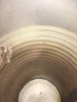
From the last photo that you posted it looks like the flame is sensed between the ignitor and the perforated combustion chamber "can". It wouldn't hurt to clean up the perforated metal directly across from the ignitor.
Well swamp rat ,8James and all, I went to town and bought a trms 6000 multi meter to confirm the sensing , and yep it read a a few microampers when work up and lite then boom it was out as the flame dropped out, gas stoped. So reconfirmed igniter yep good so I bit the bullet and took the whole gas module and blower off to get to the flame holder checking everything for a sign of damage, all was good so check out the pic from the fh.


Last edited:
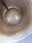
Run out of rooom so , then found this, a few bindis and foot ticklers (see pic ) could these little bindi eyes sucked in by the blower make a flame drop?? Cleaned the pipe , it looked spick and span. So put the whole show back together and bingo!! She fired up and stayed on. Fluck? Shut her down and started again , again and again. So I’m rechecking the gas and the vdc sensing and will be doing a differential check when I get a T . If something screws up I,ll post. But I want to thank swamprat and James for their knowledge and time I hope this tread helps other pentairers workout how moody this little child can be. Time for many beers  and it’s my shout. Cheers glen tx.
and it’s my shout. Cheers glen tx.Attachments

OK, hopefully it will continue to work now. 

 www.troublefreepool.com
Become a TFP Supporter
Help Support TFP Trouble Free Pool is run by a dedicated group of volunteers that … Read more…
www.troublefreepool.com
It might have been a bad ground path.
It's a known problem that they have made a fix for.
It's a known problem that they have made a fix for.
swamprat69
Well-known member
The Trane "Voyager" commercial rooftop units were also designed with a combustion air blower and negative pressure gas valve. It exhibited a number of problems that were not seen in induced draft units, E.g. bolts that were frozen in place by rust when attempting to disassemble in order to service the unit etc.. Also unlike induced draft systems where the parts needing to be serviced are at the inlet and outlet of the heat exchanger/ combustion chamber, flame sensing takes place inside the heat exchanger/ combustion chamber necessitating taking it (the "drum") apart in order to troubleshoot. There was also a similar residential furnace made in this style which was also found to be somewhat "finicky" in operation and difficult to work on.
Thanks James - The aux ground path (as set out in the fenwal kit) i had put in earlier. So i reckon it must have been these little bindi eyes swirling around in the mixer. Have you ever heard of such a thing?It might have been a bad ground path.
It's a known problem that they have made a fix for.
Or maybe she,s a heater that needed a bit of tlc on every level to come back to sync. Gas / flame sense and the stuff in the holder. You call it in many of your other post that i.ve read, that everything has to be in balance and just right for this system to work. So thanks mate. i was able to give wife a spa yesterday and " happy wife is a happy life" txgi
Thread Status
Hello , This thread has been inactive for over 60 days. New postings here are unlikely to be seen or responded to by other members. For better visibility, consider Starting A New Thread.