- Apr 10, 2018
- 6,323
- Pool Size
- 18375
- Surface
- Plaster
- Chlorine
- Salt Water Generator
- SWG Type
- CircuPool RJ-45 Plus
When we built the pool, I decided against full automation for a variety of reasons including cost, the proprietary nature of available devices, and the fear an expensive system would quickly become obsolete and unsupported. I've seen a few forums members using Raspberry PI and Arduino controllers, but that kind of technology is way above my (retired) pay grade. If your preference is high tech automation or you have programming skills no reason to read on.
I've been kicking around the idea of using a WIFI irrigation controller to control valve actuators and VS pump speeds. Valve actuators require 24 VAC power (same as most irrigation controllers) and draw .75 amps. I purchased four Intermatic valve actuators at a cost of just under $400 and hijacked the Rachio irrigation timer out of the garage. I used Alexa to set up "routines" activated by voice. Routines allow the user to set turn on/off a series of connected devices in succession, with or without pauses. The system worked good, but since an irrigation controller will power only one zone (valve) at a time, transitions between pool, spa, waterfall, and cleaner modes were taking several minutes.
I ended up purchasing two 4-channel WiFi switches at a cost of about $22 each. Through the Ewelink Smart Home app, each channel is recognized by Alexa as an individual device. The module is powered by hardwired 7-32 volts AC/DC or USB 5 volts. Since my system already used a 24 VAC transformer to power the Intellicomm II Interface Adapter, I used this to power both the modules and the valve actuators. When purchasing a power source, choose one that puts out 24 VAC power and can handle the amperage draw of all valves combined.
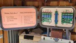
I've included a photo of the relay board below. Each valve actuator can be run in both directions off one relay. Each relay has three connections: Common (24 VAC power), NC (normally closed) and NO (normally open). The actuators have three connections. The black lead goes to the other side of the AC power. The other two actuator leads (red and white) power the valve in separate directions. One lead goes to NC and the other to NO. When power is shut off, the motor turns one way and when powered up, it turns the other way. A limit switch in the actuator cuts power to the motor when the valve reaches it's resting position.
The Intellicomm II Interface Adapter installed in my system allowed external control of four pump speeds via the Intelliflo VS data cable. I had two inputs wired to mechanical timers and two to rocker switches in the load center. I wired into two of the four inputs and connected each to an individual relay on the second 4-channel Wifi switch. Each is recognized by Alexa as a device (Pump Low Speed and Pump Med Speed). I left alone two of the mechanical timer and switch inputs on the Intellicomm, but may connect them to the open relays in the future.
I named my valves "Pool Return" "Pool Suction" "Cleaner" and "Waterfall". When "Pool Return" is set to ON, water goes to the pool. When OFF, water goes to the spa. When "Pool Suction" is set to ON, water comes from the pool. When OFF, water comes from the spa. Same idea holds true for the two remaining valves.
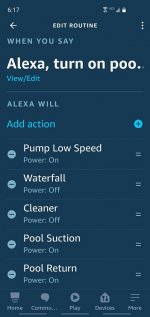
I programmed four individual routines in the Alexa app, Pool Mode, Spa Mode, Waterfall Mode, and Cleaner mode. I included a screenshot of the Pool Mode program below. The first three modes above are intended for use when the pool is in use. Modes can be changed through Alexa by voice or by buttons in the routines section of the app. I found the system operates flawlessly, so far. I'm gonna work on daily schedules, but for now, the pump will remain on the reliable mechanical timer or an internal pump program.
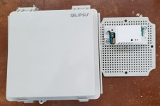
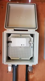
I used a Rachio outdoor enclosure ($30) to house the switches and mounted it above my load center. The relays have four manual switches which correspond with the relay assignments...something that may come in handy for manual control of individual valves or pump speeds. The WiFi switch I purchased also comes with a remote (a bit of a novelty). Each button can be programmed to control on/off functions of several relays. It won't get much use.
I know this won't be everyone's cup of tea, but it works out great for my needs. Total cost (excluding the actuators) was about under $100. Add to that a few bucks for a 24VAC transformer and you have full automation of the valves. Pump control is dependent upon your own set up.


Last edited:


