Jandy JXi 400N Not Igniting - Help

b2cperson

Member
May 7, 2021
12
North Carolina
I opened my pool two weeks ago. At the time, I was able to fire up the heater and it ran for about 20 minutes before mysteriously shutting down. I decided to troubleshoot this on my own which may have been my first mistake :) I used the troubleshooting guide in the "Workbook JXi Pool & Spa Heater" provided by Zodiac.

Background:
Saltwater Pool & Spa
Built in 2015
All Jandy equipment

When I use the Aqualink remote to turn on the heater, I choose a temperature well above the current water temp.
Behavior
  1. Heater Blower turns on and remains on
  2. Igniter glows
  3. Hear a clicking sound, ignitor stops glowing
  4. Approx 30 seconds later Ignitor begins glowing again, same as above
  5. Tries 3rd time, then shuts down
Steps Taken
According to the troubleshooting manual, I was supposed to skip to step 13 if the blower was on and working. Everything else seemed to checkout. I have now replaced:
  1. The Gas Valve
  2. Water Pressure Switch - Brass nuts were cracked anyway
  3. Ignition Control
Observations:
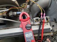
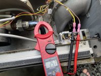
  • I noted that the two wires connected to the Exhaust Temp Fusible Link, were blackened and charred. I cut those ends off and re-crimped new ends, but did not attempt to replace the Exhaust Temp switch. According to the troubleshooting steps in the manual, the fusible link was fine. Could that possibly be the issue? (See Photo)
  • It does not seem like the gas valve is opening and releasing gas
  • The main gas Valve is on
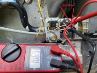
  • Gas pressure incoming is measured at 7.6 in WC
Any help or suggestions about what might be the cause of this? I am at a loss and don't want to waste any more money on parts until I am sure of what it might be. Any and all advice is welcome.

Thanks,
Mike
 

Attachments

  • Fusible Link.jpg
    Fusible Link.jpg
    382.6 KB · Views: 38
Does the gas pressure change at all when the heater tries to ignite?

Are you sure that all gas valves back to the meter are On?

Do you have more pictures of everything?
 
Does the gas pressure change at all when the heater tries to ignite?

Are you sure that all gas valves back to the meter are On?

Do you have more pictures of everything?
A few more items.
1) I confirmed that the gas pressure never changes even when the call for gas comes on.
2) Yes, all the upstream gas valves back to the meter are on. Just to double check I removed on the 3/4" plugs between the gas pressure valve and the heater. I then opened and the gas valve, located next to the heater, and plenty of gas came out.
3) I have retested everything per the Jandy "Workbook JXi Pool & Spa Heater" for troubleshooting and can't find anything obviously wrong.
4) I cut off the burned connectors at the fusible link and re-attached new female connectors.
5) What pictures would you like to see? Anything in particular?

Gas Valve:
I don't think the gas valve is opening to supply gas.
1) I test the voltage between the wire brown and yellow wires at the valve. After the ignitor glows, I hear a clicking sound and see 26.2V across the brown and yellow wires for approximately 4-5 seconds. Then the voltage drops to 0.

NOTE: If I leave the brown and yellow wires attached to the male spade disconnects on the valve AND I place my test leads directly on the exposed portion of the male spade disconnect, I NEVER see the 26.2V during the startup. I ONLY see the 26.2V if I remove the brown and yellow wires from the gas valve and place my tester leads in the ends of those wires.

2) To validate now gas, I loosened the 3/4 gas coupler that connects the gas valve to the combustion chamber. I then ran through the startup, with my hand on the gas shutoff valve for emergencies. Absolutely no gas was released that I could smell. For me, this confirms the gas valve is not opening.
 

Attachments

  • IMG_2245.jpg
    IMG_2245.jpg
    583.2 KB · Views: 22
  • IMG_2214.jpg
    IMG_2214.jpg
    384.3 KB · Views: 18
  • IMG_2208.jpg
    IMG_2208.jpg
    415.3 KB · Views: 18
  • IMG_2209.jpg
    IMG_2209.jpg
    323 KB · Views: 17
  • IMG_2210.jpg
    IMG_2210.jpg
    415.8 KB · Views: 18
  • IMG_2211.jpg
    IMG_2211.jpg
    573.8 KB · Views: 22
  • IMG_2206.jpg
    IMG_2206.jpg
    419.6 KB · Views: 24
  • IMG_2157.jpg
    IMG_2157.jpg
    437.8 KB · Views: 19
  • IMG_2155.jpg
    IMG_2155.jpg
    453.3 KB · Views: 16
  • IMG_2154.jpg
    IMG_2154.jpg
    628.8 KB · Views: 19
I have now replaced:
  1. The Gas Valve
  2. Water Pressure Switch - Brass nuts were cracked anyway
  3. Ignition Control
The gas valve does not look new. Where did you get it?
NOTE: If I leave the brown and yellow wires attached to the male spade disconnects on the valve AND I place my test leads directly on the exposed portion of the male spade disconnect, I NEVER see the 26.2V during the startup. I ONLY see the 26.2V if I remove the brown and yellow wires from the gas valve and place my tester leads in the ends of those wires.
Where are you measuring the voltage for the gas valve?

Are you measuring AC or DC?

Where are you measuring the gas pressure?
 
The gas valve does not look new. Where did you get it?

Where are you measuring the voltage for the gas valve?

Are you measuring AC or DC?

Where are you measuring the gas pressure?
Gas Valve
Photos are of the old gas valve when I was troubleshooting. There is a brand new one installed at this time. I can provide photos if that helps.

I measured the voltage at the gas valve two ways. 1- I pulled the yellow and brown wires off the valve and inserted my probes, one to each end. I am using AC for the testing. I then start up the heater using the remote. After about 30-45 seconds the ignitor is glowing orange. I hear a click and the voltage across those two wires hits 26.2 AC for about 5 seconds.

The second way I tried to measure was by leaving the brown and yellow wire attached to the valve. I then placed my probes on the exposed portion of the male connectors that stick out from the gas valve. I then do all of the steps above but I never see any voltage between the brown and yellow connection points. FYI the brown and yellow wires are connected to them for this test.

The pressure was measured from the 1/8" fitting on the inlet side of the gas valve (the side closest to the gas supply). I used a digital tester.
 
If you are getting voltage with the wires off of the terminals but not when the wires are connected to the terminals, that points to a short circuit.

Are you sure that the wiring to the new valve is exactly right?
 

Enjoying this content?

Support TFP with a donation.

Give Support
If you are getting voltage with the wires off of the terminals but not when the wires are connected to the terminals, that points to a short circuit.

Are you sure that the wiring to the new valve is exactly right?
Please new photos showing the new gas valve, new water pressure switch, and testing locations and voltage for the gas valve during startup. Thoughts?
 

Attachments

  • Gas Supply.jpeg
    Gas Supply.jpeg
    689.7 KB · Views: 21
  • New Gas Valve.jpeg
    New Gas Valve.jpeg
    444 KB · Views: 19
  • New Water Pressure Switch.jpeg
    New Water Pressure Switch.jpeg
    424 KB · Views: 17
  • Valve During Startup 1.jpeg
    Valve During Startup 1.jpeg
    474.7 KB · Views: 20
  • Valve During Startup 2.jpeg
    Valve During Startup 2.jpeg
    481.2 KB · Views: 16
  • Valve During Startup 3.jpeg
    Valve During Startup 3.jpeg
    470.1 KB · Views: 13
  • Valve Pre-Startup.jpeg
    Valve Pre-Startup.jpeg
    427.7 KB · Views: 15
  • Valve Voltage Test.jpeg
    Valve Voltage Test.jpeg
    401 KB · Views: 17
  • Gas Test Plug.jpeg
    Gas Test Plug.jpeg
    257 KB · Views: 24
  • Top View New Gas Valve.jpeg
    Top View New Gas Valve.jpeg
    488.9 KB · Views: 24
Please new photos showing the new gas valve, new water pressure switch, and testing locations and voltage for the gas valve during startup. Thoughts?
Forgot to confirm that testing the voltage between the brown and yellow connector, directly at the valve as seen in the "Valve Voltage Test" image, shows 0.00 volts AC when the heater goes through a startup. Meaning when I hear a click, I don't see any voltage like I do when testing the voltage with the two wires disconnected as in the "Valve Startup 3" photo.
 
Have you checked the resistance (ohms) of the 2 gas valve solenoid coils? Remove the yellow and brown wires from the gas valve. Remove the 2 solenoid coil wires from the gas inlet side of the gas valve ( by where you took the pressure reading). Leave the gas valve switch in the "on" position. Measure the resistance at the 2 solenoid coil wires that you removed from the inlet side of the gas valve. Measure the resistance at the 2 gas valve terminals that you removed the 2 solenoid coil wires from to obtain the resistance of the second gas valve solenoid coil. Both these readings should be in the neighborhood of approximately 50 ohms give or take a little. If they are significantly more or less, you have a problem with the gas valve. If your ohm readings are good, you may have a problem with the gas valve relay contacts in the Fenwal. From what I understand, you never get any flame/heat during the ignition sequence and never smell any raw gas odor from the vent discharge...correct? Does the Fenwal ignition module show any fault codes? The sequence of operation for the Fenwal is : 15 seconds blower, 40 seconds ignitor warm up and 7 seconds power to gas valve to prove ignition. Have you checked the resistance of the ignitor? It is also used as a sensor to prove the ignition/flame.
 
You are taking the brown and yellow wires off of the gas valve and doing nothing with them. Then remove the 2 wires on the inlet side of the gas valve that go to the visible solenoid coil ( the black part that looks like a truncated teardrop). Measure the resistance between the 2 wires you removed from the solenoid coil on the inlet side of the gas valve. Then measure the resistance at the 2 gas valve terminals that you removed the solenoid coil wires from with the gas valve on/off switch in the "on" position.
 
You are taking the brown and yellow wires off of the gas valve and doing nothing with them. Then remove the 2 wires on the inlet side of the gas valve that go to the visible solenoid coil ( the black part that looks like a truncated teardrop). Measure the resistance between the 2 wires you removed from the solenoid coil on the inlet side of the gas valve. Then measure the resistance at the 2 gas valve terminals that you removed the solenoid coil wires from with the gas valve on/off switch in the "on" position.
Ok. I tested as you described and attached photos just to be sure I am testing the correct items.
1) Resistance at the terminals of the solenoid closest to the gas inlet is 106.9 Ohms
2) Resistance between the two light brown wires, that were removed from the solenoid connectors, 19.5 Ohms
3) The "old" gas valve that I removed measures the same as the new one that is currently installed + or - 0.5 Ohms
4) Resistance at the Ignitor is 58.6 Ohms
 

Attachments

  • Resistance at Ignitor.jpeg
    Resistance at Ignitor.jpeg
    399.7 KB · Views: 20
  • Resistance at Solenoid Terminals.jpeg
    Resistance at Solenoid Terminals.jpeg
    400.5 KB · Views: 18
  • Resistance at Solenoid Wires.jpeg
    Resistance at Solenoid Wires.jpeg
    442.5 KB · Views: 20
Any other ideas for me? The gas valve is clearly getting voltage but does not activate the solenoid. This would seem to suggest a bad gas valve but I already replaced the gas valve with a brand new one. What are the chances I received a bad gas valve out of the box?

Is it possible the gas valve is not receiving enough amperage to activate the solenoid? I know the brown and yellow wires are providing 26.2 V AC to the gas valve as part of the ignition sequence.

I am at a loss and could use some guidance.
 

Enjoying this content?

Support TFP with a donation.

Give Support
Thread Status
Hello , This thread has been inactive for over 60 days. New postings here are unlikely to be seen or responded to by other members. For better visibility, consider Starting A New Thread.