I have an Intellitouch i9+3 and Expansion Center i10X that are connected to an i-link adapter. Recently we developed an issue where the Expansion Center stopped working. The lights next to the button are still on and it still seems to run on a schedule but the buttons do not work I cannot put it into service mode and run the pumps and lights manually. There also appears to be no power to the antennae (its not a Wi-Fi antennae). The remote control obviously cannot sync to it because the antennae is not receiving any power or maybe the antennae is dead itself.

Intellitouch i9+3 and Expansion Center i10x not working properly 520949 receiver
- Thread starter koltontaylor
- Start date
You are using an out of date browser. It may not display this or other websites correctly.
You should upgrade or use an alternative browser.
You should upgrade or use an alternative browser.
hey Kolton, give us a little more info...
and when you say there's no power to the antenna, is that on the expansion, main intellitouch or both? if you have a multimeter, measure the dc voltage on the comm port's red/black terminals - do this on both boards and let us know what you get
in the quote above, are you talking about the expansion center board or the main intellitouch?The lights next to the button are still on and it still seems to run on a schedule but the buttons do not work I cannot put it into service mode and run the pumps and lights manually
and when you say there's no power to the antenna, is that on the expansion, main intellitouch or both? if you have a multimeter, measure the dc voltage on the comm port's red/black terminals - do this on both boards and let us know what you get
The wires for the antenna appear to come from the expansion board. The expansion board is the one with the issues. The main board seems to be running fine. I will buy a multimeter today and update you. What should the dc voltage be?
Sorry didn’t realize I could reply directly. Not sure if that’s how you get alerts. See response above. Thanks!hey Kolton, give us a little more info...
in the quote above, are you talking about the expansion center board or the main intellitouch?
and when you say there's no power to the antenna, is that on the expansion, main intellitouch or both? if you have a multimeter, measure the dc voltage on the comm port's red/black terminals - do this on both boards and let us know what you get
no worries... I get an alert whenever anybody adds anything to the thread ")
about the voltage... the comm port is listed as 12 volts dc, but you'll see something 14-16 volts. if it's less than 12 then there's an issue.
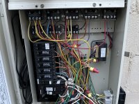
see if you can unplug the antenna from the expansion board: you'll have to remove the 2 screws in the top corners of the plastic bezel/frame and then flip it down... then you'll see the two com ports (J7 and J8) in the lower left. your antenna will likely be plugged into J8, and the entire 4-position black terminal block will pull up off the board (so you don't have to unscrew any wires). actually - send a photo of the whole board once you have it flipped down
about the voltage... the comm port is listed as 12 volts dc, but you'll see something 14-16 volts. if it's less than 12 then there's an issue.
see if you can unplug the antenna from the expansion board: you'll have to remove the 2 screws in the top corners of the plastic bezel/frame and then flip it down... then you'll see the two com ports (J7 and J8) in the lower left. your antenna will likely be plugged into J8, and the entire 4-position black terminal block will pull up off the board (so you don't have to unscrew any wires). actually - send a photo of the whole board once you have it flipped down
Last edited:
These are the photos I have. I took them yesterday. I have not been able to do the voltage meter test yet.no worries... I get an alert whenever anybody adds anything to the thread
about the voltage... the comm port is listed as 12 volts dc, but you'll see something 14-16 volts. if it's less than 12 then there's an issue.
see if you can unplug the antenna from the expansion board: you'll have to remove the 2 screws in the top corners of the plastic bezel/frame and then flip it down... then you'll see the two com ports (J7 and J8) in the lower left. your antenna will likely be plugged into J8, and the entire 4-position black terminal block will pull up off the board (so you don't have to unscrew any wires). actually - send a photo of the whole board once you have it flipped down
Attachments
-
 IMG_9302.jpeg508.4 KB · Views: 4
 -
 IMG_9300.jpeg457.6 KB · Views: 5
 -
 IMG_9299.jpeg321.1 KB · Views: 5
 -
 IMG_9298.jpeg537.7 KB · Views: 4
 -
 IMG_9292.jpeg470.8 KB · Views: 4
 -
 IMG_9291.jpeg555.8 KB · Views: 4
 -
 IMG_9290.jpeg347.7 KB · Views: 4
 -
 IMG_0432.jpeg349.2 KB · Views: 4
 -
 IMG_7945.jpeg378.2 KB · Views: 4
 -
 IMG_7944.jpeg380.5 KB · Views: 4
These are the photos I have. I took them yesterday. I have not been able to do the voltage meter test yet.
Attachments
great pics! and here I am trying to explain how to open these things when you clearly know how
didn't see whether you'd unplugged the antenna, but if it's still plugged in are you seeing activity on the 485 and RF link LEDs? (if you're seeing them both flash together in a sort of 6-flash repeating pattern, that's bad - but if you see a flick every second or so on the 485 and then an RF flash if you press a mobi button, that's good)
didn't see whether you'd unplugged the antenna, but if it's still plugged in are you seeing activity on the 485 and RF link LEDs? (if you're seeing them both flash together in a sort of 6-flash repeating pattern, that's bad - but if you see a flick every second or so on the 485 and then an RF flash if you press a mobi button, that's good)
No flashes whatsoever on one of the com ports I found a broken wire. I restripped it and put it back into place but it had no effect. I think no power is going to the antenna. At least that’s my theory.great pics! and here I am trying to explain how to open these things when you clearly know how
didn't see whether you'd unplugged the antenna, but if it's still plugged in are you seeing activity on the 485 and RF link LEDs? (if you're seeing them both flash together in a sort of 6-flash repeating pattern, that's bad - but if you see a flick every second or so on the 485 and then an RF flash if you press a mobi button, that's good)
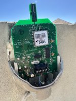
ok cool, so we can verify that once you get your meter... you can measure the supply voltage at the transceiver too to rule out a bad cable
You'll measure on the two outermost terminals (black/red):

You'll measure on the two outermost terminals (black/red):
Tom,
I would 'assume' that since the Power LED is not ON, that the antenna is not getting the 15 VDC, or the antenna module is bad.
Thanks,
Jim R.
I would 'assume' that since the Power LED is not ON, that the antenna is not getting the 15 VDC, or the antenna module is bad.
Thanks,
Jim R.
Ok great thank you can you walk me through how to measure the voltage exactly? Do I pull the wire out and touch the wire with the meter?ok cool, so we can verify that once you get your meter... you can measure the supply voltage at the transceiver too to rule out a bad cable
You'll measure on the two outermost terminals (black/red):
View attachment 626128
@Jimrahbe - I agree, so I'm just trying to figure out if the problem is the transceiver or the comm port on the main board... I'm leaning toward a bad main board since the i10x expansion unit is also acting up. measuring the voltage at the card terminals is just a way to measure the voltage at the main board terminals that also includes the cabling in the test.
@koltontaylor - you don't have to pull any wires off or out... set your meter to read DC volts and - with the panel flipped down like you've got in your photos - touch the black meter test lead to the screw of the J7 or J8 comm port terminal block marked "blk" (black) and the other test lead on the screw for "red". (If you swap the test leads the reading will just have a negative sign in front of it)
@koltontaylor - you don't have to pull any wires off or out... set your meter to read DC volts and - with the panel flipped down like you've got in your photos - touch the black meter test lead to the screw of the J7 or J8 comm port terminal block marked "blk" (black) and the other test lead on the screw for "red". (If you swap the test leads the reading will just have a negative sign in front of it)

The two inside screws give me a reading of about .4v the outside screws give nothing. That’s when the voltage meter is set to this setting. That’s when testing the antenna directly. I get around 17 on the com ports on the expansion panel.
I was able to trace where the antenna wires went. They go to the main board and it’s say 17v when I touch the outside/inside cables out ole me to touch. But then the antenna says nothing. Does this mean the wire is bad? I checked the expansion panel and regular panel. All have same voltage on the com ports.
don't mess with the two inside screws too much... those are the data lines and they're easy to damage.
but yeah, if you're getting 17volts on the outside screws of the comm port at the outdoor panel and nothing at the antenna, then it seems like the cable is broken.
You might want to power down, disconnect the terminal block from the antenna card, power back up and measure the voltage on the antenna's two outside screws again. (it's not strictly necessary but eliminates the possibility that the antenna is causing the voltage problem... in reality, if the antenna was drawing too much power and killing the voltage, then you wouldn't be seeing 17volts at the outdoor comm port either)
I usually temporarily replace any questionable cable with a short length to see if fixes the problem... just power everything off before you mess with the comm port screws or you could damage the boards!
in reality, if the antenna was drawing too much power and killing the voltage, then you wouldn't be seeing 17volts at the outdoor comm port either)
Yep..
Thanks,
Jim R.