IC40 install with iAqualink

FTC3

0
Jul 7, 2012
62
Las Vegas
Couple of questions. I’m installing an IC40 with the iAqualink system. Is there any way these two will communicate with each other to where I can control it with my app? Or will I be running the IC40 independantly?

Second, question on wiring... I’m running a Pentair Intelliflo pump with my iAqualink, how would I wire the salt transformer into this setup? There is a flow sensor built into the IC40 already, correct? Do I simply wire in the 220v into a new GFI breaker or through one of the relays?

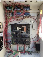
Attached is a picture of my set up. The wires highlighted in green are the pump wires to the upper left relay.

Many thanks in advance
 

Attachments

  • 301400ED-A571-4AA1-B770-D13D744FB88C.jpeg
    301400ED-A571-4AA1-B770-D13D744FB88C.jpeg
    509 KB · Views: 17
The IC40 will not communicate with the Aqualink.

The IC40 needs to be powered off when the pump is off. The flow switch is a secondary safety switch.

I have an IntelliFlo pump and IntelliChlor and have the pump programmed to run 24/7. Both the pump and IntelliChlor are connected to the filter/pump relay. So they are both powered up or down by the Aqualink.
I figured as much but not concerned as I don’t mess with the chlorine output very often.

Do I wire it on top of the pump wires on the same relay?
 
Do I wire it on top of the pump wires on the same relay?

You have some device wired to the LINE side of the relay and a device wired to the LOAD side of the relay. Assuming the pump is wired to the LOAD side then put the SWG wires to the left of the screws to be switched with the pump.
 
  • Like
Reactions: FTC3
You have some device wired to the LINE side of the relay and a device wired to the LOAD side of the relay. Assuming the pump is wired to the LOAD side then put the SWG wires to the left of the screws to be switched with the pump.
I wired it off the same relay as the pump and heater but for some reason the SWG is always powered on. Am I correct, the SWG should have no power until the pump comes online?
 
I wired it off the same relay as the pump and heater but for some reason the SWG is always powered on. Am I correct, the SWG should have no power until the pump comes online?

SWG should be off when pump is off.

You wire the SWG power to the LINE side screws or the LOAD side screws of the relay?

Post a pic of the relay wiring and identify the pump wires, SWG wires, and hot wires.
 
  • Like
Reactions: FTC3
SWG should be off when pump is off.

You wire the SWG power to the LINE side screws or the LOAD side screws of the relay?

Post a pic of the relay wiring and identify the pump wires, SWG wires, and hot wires.
Thanks for the quick reply. It was my mistake. I was certain I wired it to the LINE side but I had it backwards. Switched the wires and all is good. Thanks again!
 

Enjoying this content?

Support TFP with a donation.

Give Support
Thread Status
Hello , This thread has been inactive for over 60 days. New postings here are unlikely to be seen or responded to by other members. For better visibility, consider Starting A New Thread.