How's my solar heater design? Will it work? Where to put the vacuum breaker?

everthustodeadbeats

Active member
Jul 12, 2023
32
Detroit, Michigan
Pool Size
35000
Surface
Plaster
Chlorine
Liquid Chlorine
I'm almost done with a new solar system and I've got it mostly put together, dry fitting the plumbing. Before I glue everything up, I wanted to get y'all's take on it, make sure there aren't glaring design flaws, etc.

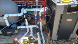
The overview is, there will be five Fafco 2x20 solar collectors stacked beginning at ground level. I didn't want to put it on the roof, partially because I'm concerned by 1.5HP single speed pump can't handle the 20'+ rise. I'm hoping it will be sufficient for the current design, in which the highest the water will get will be about 8-10 feet. The frame I built is at apprx a 30 degree slant, about 30 feet away from the pad. The water will enter the panels at the farthest point from the pump (at the bottom, obviously) and exit at the high point closest to the pump, and then travel the way back to the pump at about 8 or 10 feet above the ground. I have check valves both going from the pad to the solar, and going from the solar back to the pad (it meets back up with the plumbing right before the gas heater, which hopefully will not be needed as often).

Given that the path from the pump to the solar is at the ground level (using flexi-PVC), can the vacuum breaker also be on the ground at the lowest part of the collectors on the exit side (see diagrams)? I've read the threads about vacuum breaker placement but it seems in those cases the solar panels were on a roof. Also, question: I understand that the purpose of a vacuum breaker is to help the solar panels drain when not in use, but where does it drain to on the supply side? Since I have check valves going from the pump to the solar, it seems there's no way for the water to go backwards and leave the panels. Am I missing something? How does it ever drain?

Thanks for any input!

Diagram:
Solar Fig1b.png
Photo:
Pool Solar 1.jpg

Pad detail:
Solar Fig2 (Pad detail).png

Pool pad.jpg
Pool Solar Diagram 3 (side view A).png
 
Last edited:
The overview is, there will be five Fafco 2x20 solar collectors stacked beginning at ground level. I didn't want to put it on the roof, partially because I'm concerned by 1.5HP single speed pump can't handle the 20'+ rise.
1.5 HP is plenty big for a two story house. A number of years ago, I ran my panels with a 1/2 HP pump on a two story roof (25') and no problem. The head curve determines if there is enough lift for the panels and nearly every residential pool pump can handle a two story house. Only Intex are too small.

Given that the path from the pump to the solar is at the ground level (using flexi-PVC), can the vacuum breaker also be on the ground at the lowest part of the collectors on the exit side (see diagrams)?
You really don't want the VRV that low. When the pump shuts, water may leak out. It needs to have at least a few feet of height above the pool. Upper left corner is much better.

I've read the threads about vacuum breaker placement but it seems in those cases the solar panels were on a roof. Also, question: I understand that the purpose of a vacuum breaker is to help the solar panels drain when not in use, but where does it drain to on the supply side?
That is why you need some elevation on the supply side. It is gravity drain so unless those pipes slow downward towards the pad and don't ever increase in elevation, they will not fully drain.

Since I have check valves going from the pump to the solar, it seems there's no way for the water to go backwards and leave the panels. Am I missing something? How does it ever drain?
Besides the elevation issue, you put the supply side check valve in the wrong locations. It needs to go right after the filter and before the solar valve. Also, that valve should be a solar valve, not a standard 3-way valve or again, the supply side will not drain.
 
  • Like
Reactions: everthustodeadbeats
You really don't want the VRV that low. When the pump shuts, water may leak out. It needs to have at least a few feet of height above the pool. Upper left corner is much better.
Thanks, that is exactly the kind of feedback I was looking for.

Besides the elevation issue, you put the supply side check valve in the wrong locations. It needs to go right after the filter and before the solar valve. Also, that valve should be a solar valve, not a standard 3-way valve or again, the supply side will not drain.
Okay, good to know my instincts were correct about it not draining. I seem to recall that the Pentair draining solar valve is the only one on the market. Is that true, and if so does that mean they have a total monopoly, such that one cannot set up a solar heater without this one specific product? Is there no standalone alternative, i.e., not part of a diverter valve?

It seems like what I want is something sort of like a check valve, but where instead of blocking off reverse flow completely (where Forward flow = Path 1; Reverse flow = blocked), it instead sends a reverse flow down a different path, such as to a drain or to the pool (so: Forward flow = Path 1; Reverse flow = Path 2). Does such a valve exist in the plumbing world?
 
Separate question: is there any advantage in keeping the return pipe elevated until immediately prior to rejoining the pad plumbing, as shown in my diagrams?

Or would the flow mechanics be the same if I dropped the pipe straight from the solar panel exit down to the ground, and then snaked the return line back to the pad at ground level, right next to the supply line?
 
The solar valve has a built in check valve so when the solar valve shuts off solar, it can still drain but will not allow water back into the solar supply.

What I outlined is how solar is normally installed and proven to work well.
 
No matter what you do, you will likely need to manually drain both pipes when winterizing to prevent free damage.

Whenever solar pipe is plumbed below the pad plumbing, self draining will be an issue.
 
No matter what you do, you will likely need to manually drain both pipes when winterizing to prevent free damage.

Whenever solar pipe is plumbed below the pad plumbing, self draining will be an issue.
Yes, I anticipated manually draining at the end of the season during winterizing. I will certainly do that.

On a day-to-day basis during the summer, I expect the solar will be on most days during daylight hours, and will only turn off (a) if there's no sun due to very overcast or raining conditions, (b) if the weather gets cold, and (c) at dusk (and the pump is set to turn off nightly from 10pm to 8am).

(I don't have a full featured solar controller; I will be writing my own rules and logic for the wifi-based relays and switches. I am sure I will need to experiment a little on the triggers for turning the solar on and off via the actuated valve.)

How bad is it for water to remain in the solar panels for a couple hours at a time, maybe a day at most, during the season?
 
If water remains in the panels without water flow, it will continue to heat up and can get so hot it will soften the plastic in the panels and pipe and they could deform and collapse. You might want to rethink placing the panels on the roof. It solves many of the issues that you will be dealing with.


1717125970200.png
 
  • Like
Reactions: everthustodeadbeats
Besides the elevation issue, you put the supply side check valve in the wrong locations. It needs to go right after the filter and before the solar valve. Also, that valve should be a solar valve, not a standard 3-way valve or again, the supply side will not drain.

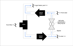
Unfortunately I don't have any room between the filter and the 3-way valve. And having just bought a regular 3-way valve I don't want to go out and buy the Pentair solar drain-down version too. I'm aware that I can drill a hole in the regular 3-way valve to make it act as a solar valve, but I think I figured out a different way that will allow me to keep the check valve after the 3-way. I think all I need to do is to add a tee to both the solar supply and return lines (between the two check valves) and connect them with a pass-through. A ball valve in the pass-through can ensure that only a tiny flow of water bypasses the solar panels and goes straight to the return. I would also probably use reducing tees to make the pass-through line using a smaller pipe to begin with, maybe 1/2" or 3/4".

Diagram:
Solar Passthrough.png
Does this look like it will work? Seems to me that this is identical to the flow with a solar diverter valve.
Also wouldn't mind getting @Dirk 's take on the matter.

Thanks!
 
Won't work. When the pump shuts off, the panels will drain through the supply side and return side pipes. The return side will flow backwards through the filter which you will want to avoid. If you want to do it that way, you need a check valve on both sides of the 3-way pointing away from the filter.
 

Enjoying this content?

Support TFP with a donation.

Give Support
Won't work. When the pump shuts off, the panels will drain through the supply side and return side pipes. The return side will flow backwards through the filter which you will want to avoid. If you want to do it that way, you need a check valve on both sides of the 3-way pointing away from the filter.
Interesting, I never thought about it going backwards through the regular return (toward the gas heater), after it has successfully passed the solar check valve. You're right, there remains one path on the return without any check valve. I suppose I could add a check valve on both sides of the 3-way.

Prior to adding the solar I've never had a check valve between the filter and the gas heater, and the flow does back up a bit when the pump turns off, but not that much, not enough to mess up the filter (as far as I know). Does having solar panels make it worse or more of a risk?
 
Sorry, what little I know about solar systems is about roof top. I don't have any experience with ground mount. I would defer to Mark. That said...

Is your roof anything like your neighbor's, who has an ideal solar panel roof? If so, I agree, put 'em up there. I apologize in advance if the following was covered, as I don't have time today to study the whole thread (but I will). Just "first impressions." And pardon the "tough love" style:

I'm sure you spent a lot of time and effort on your array, but that is a monster. Is that really the only place for it? Are you and your family going to be OK looking at that thing forever? (They're ugly enough up on the roof!) If I was your neighbor, I'd be furious about that thing. Is your local municipality OK with that (local codes and all)? It certainly wouldn't be in my town.

The panels look to be woefully unsupported. Horizontal panels were not the correct choice for that. Not only will the sags tend to tear the tubes and manifolds apart, they will create high and low spots that will impact heating efficiency. What about wind load? There doesn't appear to be anywhere near enough structure. It looks like it might collapse under it's own weight, let alone full of water. Add some high winds and you've got a potential danger/lawsuit on your hands.

At quick glance, it looks like your "to solar" check valve is in the wrong place. It's not doing anything. It won't be doing anything when water is flowing to the panels when the solar is engaged, and when the solar is off, and the solar valve is in the "solar off" position, no water is going to flow back in that direction anyway. In a roof-top system, that check valve would need to be before the solar valve, either between the solar valve and the filter, or between the filter and the pump. Either position would do the same job, preventing backflow though the filter. But I can't say or not if that's the correct approach for a ground-mount system.

You'd also likely get better heat transfer on the roof, because of the increased exposure to the sun. The angle of the sunlight is less important for solar heaters than, say, PV solar, but your array is almost perpendicular to Earth, parallel would be better.

Again, sorry if this was already considered and covered, those are my initial impressions. And I realize this was not the "looks good" you were looking for, but it is what it is.
 
  • Like
Reactions: mas985
Interesting, I never thought about it going backwards through the regular return (toward the gas heater), after it has successfully passed the solar check valve. You're right, there remains one path on the return without any check valve. I suppose I could add a check valve on both sides of the 3-way.
As Dirk pointed out, you could add a check valve to the filter inlet although I am not a big fan of that because debris can collect on the check valve and prevent it from sealing.

Prior to adding the solar I've never had a check valve between the filter and the gas heater, and the flow does back up a bit when the pump turns off, but not that much, not enough to mess up the filter (as far as I know). Does having solar panels make it worse or more of a risk?
The check valve is primarily for solar installations. The solar panels are elevated and when the pump shuts off, all that water comes rushing into the plumbing very quickly (gravity drain) even before the solar valve has a chance to close so having a valve on the supply side is also advisable. Backflow through the filter is a real possibility. Without having these check valves just increases the probability that debris make go back into the pump impeller which could cause a clog. It is a bit like backwashing a filter through your pump.
 
  • Like
Reactions: Dirk
(I don't have a full featured solar controller; I will be writing my own rules and logic for the wifi-based relays and switches. I am sure I will need to experiment a little on the triggers for turning the solar on and off via the actuated valve.)
Just caught this one line. Good luck with that. The algorithms for generating the most efficient heating from a solar array are pretty complicated. "...experiment a little..."? Be prepared for a LOT, and ending up with something that still doesn't work all that well. What's your time worth? Solar heater controllers are only a few hundred dollars, time/torture tested and work great.

Sorry to be so blunt, but we've seen all sorts of attempts to reinvent pool solar heaters. Yours is better than most, but still seems to be circumventing a few of the tried and true methods. Solar heaters don't add all that much heat to a pool to begin with (I hope you're prepared for that), so eking out every last bit of efficiency is necessary to make them even barely worth the effort and expense. Stick with industry standard methods and equipment, and then crack a beer and get in your pool.
 
Last edited:
As Dirk pointed out, you could add a check valve to the filter inlet although I am not a big fan of that because debris can collect on the check valve and prevent it from sealing.
Absolutely. Mine is pre-filter because I didn't have room elsewhere. I would have preferred after the filter, that's the better spot.
 
  • Like
Reactions: mas985
@Dirk,

Thank you for your honesty. It's definitely better to know sooner rather than later.

Note the framing is just sort of a "proof of concept," and the plan was that if and when I successfully get the solar working I would reinforce it to be a more permanent structure. And I agree that it's not the most beautiful view, but my neighbor is okay with it since it acts as a tall privacy fence. We used to have trees providing privacy for both our pools, but the trees were so overgrown that together my neighbor and I decided to take them down, thus necessitating some other privacy barrier.

Moreover, I had some concerns (and anxiety) about a roof installation. First, I didn't know if my pump would be strong enough to reach the roof, and I didn't want to build a whole contraption on the roof if it wouldn't even work with my equipment. I thought that throwing together some 2x4s was less of a commitment to get my feet wet (so to speak) with this solar experiment. In the back of my mind I also thought that once I get the system working I would consider moving to the roof, either to move the entire array there or to add an additional array. (I have a total of 11 panels, all 2'x20', which I bought used really cheap.)

Second, my roof is not really optimally situated for solar. You mentioned my neighbor's roof, and you're right, his would be great, with a long, straight roofline pointing SE. Unfortunately, my roof does not have such a good layout. Below is the satelite view (neighbor on the left, my house on the right), and another view of my pool that shows both my and my neighbor's rooflines (the photo is looking approximately northward).
Satelite view of pool.jpgBackyard 15.jpg

As you can see, the part of my roof closest to the pool is a square-ish area that slants east and west, and there is no 20-foot stretch which is how long my panels are. The front of the house as a straight roofline, but that faces north/northwest.

But considering your and @mas985 's feedback, and also Mark's comment that even a 1/2HP pump is sufficient to get to a 2-story roof so I need not be too worried about that aspect, it sounds like I should just go for the roof.

When installing long solar panels on a roof, can I drape the panels over the ridgeline or use them in a 90 degree turn? Any other mounting recommendations? And what hardware will I need?

BTW my other thought was to build a pergola with a slanted roof in the area between the pool and the house (where the winter cover is unceremoniously dumped in the above photo), and put some panels on that. I figure I can fit 3 or 4 panels, depending on the slope I make the pergola roof. But since that is a structure that humans will hang out under, I have to actually build it right from the get-go and I can't half-Rear it like I did with the ground mount array. So I think that for the immediate term, mounting them on the roof is more realistic than the pergola, which will have to be a project for another day.
 
Last edited:
Unfortunately I don't have any room between the filter and the 3-way valve. And having just bought a regular 3-way valve I don't want to go out and buy the Pentair solar drain-down version too. I'm aware that I can drill a hole in the regular 3-way valve to make it act as a solar valve, but I think I figured out a different way that will allow me to keep the check valve after the 3-way. I think all I need to do is to add a tee to both the solar supply and return lines (between the two check valves) and connect them with a pass-through. A ball valve in the pass-through can ensure that only a tiny flow of water bypasses the solar panels and goes straight to the return. I would also probably use reducing tees to make the pass-through line using a smaller pipe to begin with, maybe 1/2" or 3/4".

Diagram:
View attachment 580830
Does this look like it will work? Seems to me that this is identical to the flow with a solar diverter valve.
Also wouldn't mind getting @Dirk 's take on the matter.

Thanks!
Interestingly, that is the way I was originally taught to install a solar pool heater. At the time, 3+ decades ago, the best teachers for solar in this country were from Florida. The best, period, were from Australia. Their way of installing works every time and included that ball valve.
Yes, having that ball valve was part of every installation. It served two purposes.
One, to allow the panels to drain properly.
Two, to adjust the flow for just the right amount to go through the panels. That was a two-man operation, or it took a lot of climbing to the roof. The valve was first open completely, the filter freshly cleaned, the pump on. One man would slowly close the valve until the panel farthest from the supply and the very opposite top was cold (indicating water was removing the heat from the entire array). The handle would be removed and that valve never touched again.
 
  • Like
Reactions: everthustodeadbeats
I'm curious about those panels, are they some commercial product or made up from parts by you? From the diagram I can't tell how water flows from one panel to another, are they connected in "parallel" or "series" (using an analogy from electricity)?

I did some elementary experiments along these lines, a few years ago. I used a huge unrolled black pvc hose as my "collector" just lying next to my pool and pumped water from pool through hose back into pool, the water flow was quite small (the pump was small) and I think I got a temperature rise of like 10 deg C but recall can't recall - I'm in Arizona so was quite interested in this.

I have a 1.5 acre plot here too, rear of house (single story, flat roof southwest stucco design) faces south so the potential for energy collection is huge, currently we can't use the pool until early April at best and it's all over for the year by October usually so solar would widen the usage window here.

We get sun, today the pool water temp is 84 and was 82 just four days ago, it will usually reach high 90s by mid/late July.
 
Last edited:
I'm curious about those panels, are they some commercial product or made up from parts by you? From the diagram I can't tell how water flows from one panel to another, are they connected in "parallel" or "series" (using an analogy from electricity)?

I did some elementary experiments along these lines, a few years ago. I used a huge unrolled black pvc hose as my "collector" just lying next to my pool and pumped water from pool through hose back into pool, the water flow was quite small (the pump was small) and I think I got a temperature rise of like 10 deg C but recall can't recall - I'm in Arizona so was quite interested in this.

I have a 1.5 acre plot here too, rear of house (single story, flat roof southwest stucco design) faces south so the potential for energy collection is huge, currently we can't use the pool until early April at best and it's all over for the year by October usually so solar would widen the usage window here.

We get sun, today the pool water temp is 84 and was 82 just four days ago, it will usually reach high 90s by mid/late July.
They are regular commercially available panels, like this one: SunHeater Universal 2, 2 ft. x 20 ft. (80 sq. ft.) Solar Heating System for In-Ground or Above Ground Pool S240U - The Home Depot
(some of the panels say SunHeater and some have a Fafco brand name, but they all look identical to me).

Each of the 4 ends of each panel is male threaded. I connected them together with threaded unions.

The header tubes (the manifolds) at both ends go straight through, so these are considered connected in parallel. The flow is from all of the left-side headers to all of the right-side headers (and obviously the ones at the bottom fill up first so the flow is also from lower to higher elevation). The flow doesn't weave back and forth or anything like you'd expect from a serial configuration.

My understanding is that if you have multiple banks/stacks of solar arrays, the individual banks should also be set in parallel. Meaning you split off the supply line with a tee and have a branch going to each bank, and then they re-merge on the way back after the solar panels (with another tee). You don't go from bank 1 to bank 2 to bank 3, etc. (i.e., serial).

More general info: Solar Pool Heaters - Further Reading
 
Last edited:

Enjoying this content?

Support TFP with a donation.

Give Support
Thread Status
Hello , This thread has been inactive for over 60 days. New postings here are unlikely to be seen or responded to by other members. For better visibility, consider Starting A New Thread.