Help with wiring Intermatic valve actuator

homegameroom

0
Bronze Supporter
Sep 23, 2015
295
Sunrise,FL
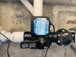
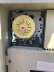
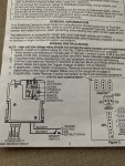
What am I doing wrong? I’ve wired this per the instructions. I have an Intermatic timer “running” it, but the valve actuator never moves on it’s own. It will operate fine if I move the switch on the side, so I believe the actuator is working just fine.

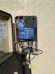
The transformer is wired to full time power and presumably works fine sine the valve will operate via the switch on the side of the actuator. . One of the black and white trigger wires is wired to constant power and the other is wired to switched power. Is this not correct? HELP!!!
 

Attachments

  • A1F625E7-7760-4C72-ACAD-4D7F4E437F52.jpeg
    A1F625E7-7760-4C72-ACAD-4D7F4E437F52.jpeg
    455.2 KB · Views: 27
  • E8A4142C-5E13-4AFF-9E18-DD17F5FA3537.jpeg
    E8A4142C-5E13-4AFF-9E18-DD17F5FA3537.jpeg
    267.5 KB · Views: 23
  • 214E21EF-439D-40F2-B46A-0CD82B45B9CC.jpeg
    214E21EF-439D-40F2-B46A-0CD82B45B9CC.jpeg
    575.2 KB · Views: 27
  • 29A298AB-7C6E-41D4-8A1E-202FBE36CA54.jpeg
    29A298AB-7C6E-41D4-8A1E-202FBE36CA54.jpeg
    507.7 KB · Views: 26
H,

Do you have three pin connector that is on the end of the actuator wire plugged into the three pin valve connector in the low voltage section?

What voltage are you using to run the transformer? What voltage are you using as the "trigger" voltage? Where is the remote switch located?

Are you using the timer as the remote switch? Show us a pic of the timer with the safety cover off and the valve driver showing the what the wire nuts are connected to.

Thanks,

Jim R.
 
Thank you for the response, Jim! It's getting too dark for pictures, so I'll have to wait a bit for that...

I do have the 3 pin connector for the valve actuator plugged in correctly - there are 2 little "darts" on one side - everything fits fine.

I'm using 120 volts for the transformer and 120 volts as the trigger voltage (and 120 volts for the timer switch). The remote switch is the pictured Intermatic timer, which is in the box next to the controller (there is another timer in the box that controls the pool pump). I assume the on-off switch on that should actuate the valve.

The timer has a hot wire hooked up to it for power (which is hooked up to one of the black/white wires for the actuator) and the other wire (hooked up to the other side of the timer switch) is hooked up to the other black/white wire.

I've measured the voltage on the 3 pin connector in the valve actuator. I assume the 24 volts should switch from one pin to the other when the switch is turned on or off; it does not.
 
One of the black and white trigger wires is wired to constant power and the other is wired to switched power. Is this not correct? HELP!!!

I would assume that the timer should have 120 volts on pin 1 (Line in) and that one of the blk/white wires (for remote switch) would be connected to pin 2 (load) then the only thing that makes sense is for the other blk/white wire to be connected to neutral... When the timer comes on, it sends 120 volts to a relay in the valve driver that sends 24 volts to the valve actuator and drives the valve one way. When the timer is off the relay is not energized the valve moves the other way...

Thanks,

Jim R.
 
Thread Status
Hello , This thread has been inactive for over 60 days. New postings here are unlikely to be seen or responded to by other members. For better visibility, consider Starting A New Thread.