Grey, let me start by saying I am not one of the experts on this site and not in any way a master at anything related to upkeep of pool maintenance issues, and I've only reappeared here in the past month due to my own water maintenance issues in my own pool. That being said, I have held a master electrician license since 1993 and have installed/replaced countless time clocks in my lifetime working commercial/industrial/residential and 100% can help you with this wiring issue. The following is written assuming no electrical knowledge so forgive if that's not the case.
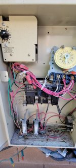
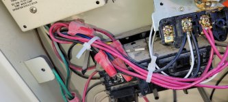
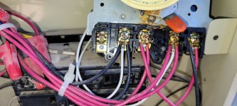
Lets start with what you have.... pic 163833.jpg shows me 5 terminals on your existing mechanical timeclock. This is a common time clock that internally has 2 separate NO(normally open) contacts(switches) that will both close when timer hits its mark (think 2 separate switches that close at the same time when timer says 'go'. Now, lets disregard the leftmost terminal(with no wires) and going from left to right with the remaining 4 terminals, lets call them A, B, C, D. So from your pic I see that there are 2 white wires with factory crimps connected to our newly designated terminals A & C (the 2nd and 4th terminal from the left). Those white wires are feeding the clock motor and confirms to me that A & C are the input power terminals. You did not indicate if your 2 loads were 120 or 240volt, assuming 240v with one being a heater, and current wiring but please advise if these loads are 120v as that may mean your current wiring is not correct(load neutrals should not be switched by clock). What is happening in your existing timeclock is this: when timer says 'turn on', internal switches close and connect terminal A to B, and terminal C to D.
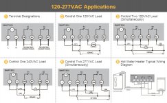
The link you provide for the new timer, per the wiring diagram shown will work as a replacement, although it does inaccurately describe it as SPST(single pole single throw). Both your existing and this new switch are technically DPST(double pole single throw- 2 single pole switches combined).
Now, to replace the timeclock:
firstly, your sketch is close, but Not correct - see below
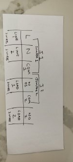
The new timer schematic shows 6 terminals L, N, com1, no1, com2, no2
existing timeclock to new - move wires as follow
A wires go to com1
B wires go to no1
C wires go to com2
D wires go to no2
New clock diagram shows L & N terminals connected internally to a 'T'. That 'T' is representing the timer motor. There should be 2 copper plate jumpers or wire jumpers that came with the new clock and should connect terminal L to com1, and N to com2. They may already be preinstalled. (remember on the old clock the white clock wires went to A and C and they must do the same on the new clock, tapping into the 2 incoming lines - L to com1, N to com2
If you have any questions at all please ask, and as a suggestion identify/mark the wires as you remove them from the old clock tag a,b,c,d, or 1 wrap of elec tape, 2 wraps, 3 wraps etc. You do not want to have those 8 wires flopping/mixing around as you remove/install the clocks and then accidentally connect wrong and short out pump or heater.