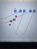
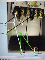
Help me wire my timer please.

Do I connect the white from the SWG to the white from the CB and not attach either to the A?
Ok,.. so connecting the neutral swg to the CB just completes the circuit, without connecting it to the pump circuit??
 
Last edited:
Do I connect the white from the SWG to the white from the CB

No, the white pigtail on the GFCI CB goes to the neutral bar,

The white neutral wire from the load goes to the neutral connection on the CB.

You need to write more explicitly to be understood on exactly what wire to what connection you are talking about.

and not attach either to the A?

You have two Independant circuits that need to be kept independent. Only the neutral in the circuit powering the timer connects to A.

Ok,.. so connecting the neutral swg to the CB just completes the circuit, without connecting it to the pump circuit??

Two independent circuits. They do not connect.
 
Each breaker will have a "pigtail" white wire that attaches to the neutral bar (bus) in your panel.
The neutral (white) wire for your pump and a connection to the A terminal of the timer will connect into the terminal marked "N" or "neutral" in the breaker for the pump. The breaker will then feed terminal 1 in your timer. Terminal 2 will be the black wire of your pump.
The neutral (white) wire for your SWG will attach to the terminal in the breaker marked "N" or "neutral." The breaker will then feed terminal 3 in your timer. Terminal 4 will be to the black wire of your SWG.
All ground (green) wires will be connected together or separately connected at the ground bar (bus). As this is a sub-panel they must be separate from the neutrals. If there is no ground bar, they can all be connected to the ground wire that is in the panel.

That is the long way of saying that your second diagram appears correct.
 
  • Like
Reactions: JeaniB
I cannot believe you guys are still here for this. Thank you so very much. You are correct I do not speak the same language B5B0143D-547C-4F77-827C-4C8FD1FCCCAE.jpegthat you do. I’m trying to learn. So riddle me this, I still don’t understand how to connect the white wire from breaker2 and the white wire from the SWG to a neutral connection without also connecting them to the circuit with circuit breaker #1.
 
I cannot believe you guys are still here for this. Thank you so very much. You are correct I do not speak the same language View attachment 404877that you do. I’m trying to learn. So riddle me this, I still don’t understand how to connect the white wire from breaker2 and the white wire from the SWG to a neutral connection without also connecting them to the circuit with circuit breaker #1.
Wait,.. do I just connect them to each other?? And am I supposed to have the neutral and the black line in under #1? The two white jumper wires are where they are when I bought the timer
 

Enjoying this content?

Support TFP with a donation.

Give Support
The SWG white wire does not connect inside the timer. It runs directly to the CB neutral connection.

Leave the thin white wires on the timer where they are.

Show us pics of the GFCI CBs.
 
  • Like
Reactions: JeaniB
The SWG white wire does not connect inside the timer. It runs directly to the CB neutral connection.

Leave the thin white wires on the timer where they are.

Show us pics of the GFCI CBs.
Do you want a pic of the GFCI CB installed, or the one that isn't installed yet?
 
Wait,.. do I just connect them to each other?? And am I supposed to have the neutral and the black line in under #1? The two white jumper wires are where they are when I bought the timer
The white wire from the SWG must be connected to the neutral terminal of the breaker that the SWG is connected to. It is a separate circuit from the pump/timeclock circuit. If you hook them all together your breakers will trip and you won't know why. Ignore the color of the wires that came with the timer. In this case color doesn't matter, and, pretty much only this case. Don't try to think of why, it will make you crazy (or crazier than this project already has).

UNDER NO CIRCUMSTANCES ever hook a black to a white wire unless you enjoy fireworks close up and want to learn how to re-set a breaker. Ignore the wires that came with the timeclock, they are not part of that equation.
 
GFCI breaker, yes. Best practice and code required. And that changes the location of where neutral wires are connected. They must be connected to the breaker neutral-load terminal, the breaker neutral wire connected to the panel neutral bus or a) the breaker is worthless as a GFCI and b) it will, most likely, just trip when energized (I've seen them not do that but that means there is something wrong with the breaker).
Ok,.. I’ve replaced breakers to 20A GFCI, ran the wire in conduit, hooked everything up at the timer. When I switch one of the breakers immediately trips. I’m not sure I understand “ neutral load terminal” .
 
Ok,.. I’ve replaced breakers to 20A GFCI, ran the wire in conduit, hooked everything up at the timer. When I switch one of the breakers immediately trips. I’m not sure I understand “ neutral load terminal” .
Never mind,.. figured it out.
My pump and swg are finally working!!
 
Thread Status
Hello , This thread has been inactive for over 60 days. New postings here are unlikely to be seen or responded to by other members. For better visibility, consider Starting A New Thread.