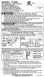
Your signature tells the story. The timer is rated as 1hp at 120v. Your pump is 1.5hp and you are running 120v. Already an apparent conflict. If you are controlling your SWG on the same timer that is likely why it burned. A better option would be an Intermatic T-103R (the R indicates an outdoor enclosure). It is a 120v timer that can control two loads. That would allow each piece of equipment to be attached to its own terminal. Yes, a mechanical timer, but highly robust. No wifi, easy to set, on/off each day.
Help me wire my timer please.
- Thread starter JeaniB
- Start date
You are using an out of date browser. It may not display this or other websites correctly.
You should upgrade or use an alternative browser.
You should upgrade or use an alternative browser.
- Jul 21, 2013
- 65,103
- Pool Size
- 35000
- Surface
- Plaster
- Chlorine
- Salt Water Generator
- SWG Type
- Pentair Intellichlor IC-60
The 40 amp rating on the timer is the maximum the timer can handle. The limit on the circuit is defined by the CB which you have at 20 amps. You do not need to match the circuit with the time. Just ensure the timer is rated at least as great as the circuit.
However the timer spec says 40 amps RESISTIVE load which is the tell that the timer is made for resistive loads like light bulbs. Motors are INDUCTIVE loads and there it says it can only handle a 1 HP motor at 120 volts.
The proper way to control a motor inductive load is with a mechanical switch like the Intermatic timers or with a contactor relay that is an electrically controlled mechanical switch. A timer like you have can be used to control a contactor relay.
Yes, many people get away with using the improper switches with incorrect loads and sometimes it bites them as your switch did when it burnt up.
Simply matching numbers does not mean you have the proper electrical equipment for the job.
Last edited:
- Jul 21, 2013
- 65,103
- Pool Size
- 35000
- Surface
- Plaster
- Chlorine
- Salt Water Generator
- SWG Type
- Pentair Intellichlor IC-60
The inductive loads are on the label. 120v-1hp. 240v-2hp.
Ah yeah, I just focused on the resistive rating and that that does not apply to a motor.
Can I run 110v to my Intermatic T104r?
I’ve been reading and reading and I’m getting conflicting info
I’ve been reading and reading and I’m getting conflicting info
No. Well to be accurate you can but the clock won't run. A T104 is a 240v timer that requires 240v for the clock. As I mentioned earlier, if you only have 120v you need a T103. It has a 120v motor but will switch two different loads if needed. A T101 is a 120v timer that will only switch 1 load.Can I run 110v to my Intermatic T104r?
I’ve been reading and reading and I’m getting conflicting info
Update
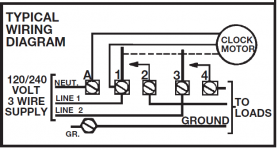
Power is ran from the breaker to the pool shed, 110V. The Intermatic T103r should be here in about an hour. Why can I not find a wiring diagram for this timer? I will wire my pump and SWG to one timer, but I’m finding no diagram to guide me. Any suggestions?
Power is ran from the breaker to the pool shed, 110V. The Intermatic T103r should be here in about an hour. Why can I not find a wiring diagram for this timer? I will wire my pump and SWG to one timer, but I’m finding no diagram to guide me. Any suggestions?
- Feb 6, 2015
- 7,809
- Pool Size
- 12300
- Surface
- Plaster
- Chlorine
- Salt Water Generator
- SWG Type
- CircuPool RJ-45 Plus
Google this:
intermatic t103 wiring instructions
Be sure any result is referencing the T103 timer
intermatic t103 wiring instructions
Be sure any result is referencing the T103 timer
I’ve spent several days doing just that.Google this:
intermatic t103 wiring instructions
Be sure any result is referencing the T103 timer
Perhaps I should be more specific. I have green, white, and black wires coming from my circuit breaker, my SWG and my pump ( 9 wires total). I need very specific instructions (pics are a bonus) as the exactly where each wire goes.
- Jul 21, 2013
- 65,103
- Pool Size
- 35000
- Surface
- Plaster
- Chlorine
- Salt Water Generator
- SWG Type
- Pentair Intellichlor IC-60
Why can I not find a wiring diagram for this timer? I will wire my pump and SWG to one timer, but I’m finding no diagram to guide me. Any suggestions?
main | 24-Hour Mechanical Time Switch, 120 VAC, 60Hz, DPST, Indoor/Outdoor Metal Enclosure, 1 Hour Interval
24-Hour Mechanical Time Switch, 120 VAC, 60Hz, DPST, Indoor/Outdoor Metal Enclosure, 1 Hour Interval

- Jul 21, 2013
- 65,103
- Pool Size
- 35000
- Surface
- Plaster
- Chlorine
- Salt Water Generator
- SWG Type
- Pentair Intellichlor IC-60
Perhaps I should be more specific. I have green, white, and black wires coming from my circuit breaker, my SWG and my pump ( 9 wires total). I need very specific instructions (pics are a bonus) as the exactly where each wire goes.

- Greens go to GR. Wire nut all greens together and pigtail to GR.
- CB black goes to 1
- Pump black goes to 2
- SWG black goes to 2
- All whites go to A. Wire nut all whites together with a white pigtail that goes to A
Last edited:
Thank you,.. exactly what I needed. It’s the terminology and abbreviations for the electrical instructions that throw me. I understand black, green and whiteView attachment 403441
Are the 9 wires all solid or stranded? Use the same solid or stranded wires 14 gauge THWN.
- Greens go to GR. Wire nut all greens together and pigtail to GR.
- CB black goes to 1
- Pump black goes to 2
- SWG black goes to 2
- All whites go to A. Wire nut all whites together with a white pigtail that goes to A
I am using 12g solid wire from the breaker. I did notice this morning that the three wires from both the pump and the SWG are stranded. Is this going to cause a problem? I’m not sure how many more problems I can take! I do however want to prevent another fire!
- Jul 21, 2013
- 65,103
- Pool Size
- 35000
- Surface
- Plaster
- Chlorine
- Salt Water Generator
- SWG Type
- Pentair Intellichlor IC-60
I am using 12g solid wire from the breaker. I did notice this morning that the three wires from both the pump and the SWG are stranded. Is this going to cause a problem? I’m not sure how many more problems I can take! I do however want to prevent another fire!
See where it says "May use two wires of the same size and type"?
Don't put two wires of different sizes and types under the same screw.
And wire nutting wires of different sizes and types does not always give a good connection.
Those are best electrical practices that an electrician would follow. Many homeowners don't.
Wiring diagram will be inside the door.Update
Power is ran from the breaker to the pool shed, 110V. The Intermatic T103r should be here in about an hour. Why can I not find a wiring diagram for this timer? I will wire my pump and SWG to one timer, but I’m finding no diagram to guide me. Any suggestions?
GFCI breaker, yes. Best practice and code required. And that changes the location of where neutral wires are connected. They must be connected to the breaker neutral-load terminal, the breaker neutral wire connected to the panel neutral bus or a) the breaker is worthless as a GFCI and b) it will, most likely, just trip when energized (I've seen them not do that but that means there is something wrong with the breaker).Uugghhh,… does my Intermatic T103r need to be connected to a GFCI breaker switch?
Ok,.. I’m beyond confused now. My pump says 20 amp, SWG max of 8 amp. I have been running this all these years to a 120v, 20amp breaker switch. The timer that burned, I assumed burned because my pump was upgraded to 1.5hp and the timer could only handle 1hp. Do I have this all done incorrectly?
I still can’t find anyone who wants to work on the electrical for an above ground pool!! I thought I had this all figured out, now I feel lost again
I still can’t find anyone who wants to work on the electrical for an above ground pool!! I thought I had this all figured out, now I feel lost again
- Jul 21, 2013
- 65,103
- Pool Size
- 35000
- Surface
- Plaster
- Chlorine
- Salt Water Generator
- SWG Type
- Pentair Intellichlor IC-60
Ok,.. I’m beyond confused now. My pump says 20 amp,
Your pump says 15 amps.
SWG max of 8 amp. I have been running this all these years to a 120v, 20amp breaker switch.
You are at the limits of a 20 amp circuit.
The timer that burned, I assumed burned because my pump was upgraded to 1.5hp and the timer could only handle 1hp. Do I have this all done incorrectly?
If the timer didn't burn something else may have overloaded.
You really need to put the SWG on a separate circuit or upgrade the circuit to 30 amp GFCI breaker with #10 wire.
I still can’t find anyone who wants to work on the electrical for an above ground pool!! I thought I had this all figured out, now I feel lost again
Proper electrical wiring is more then matching numbers and colors.
There are too many reasons, as you have seen, that the first timer could have burned.
Breakers for motors should be sized this way: Breaker size must be rated for a minimum of 125% of the full-load current of the motor it is protecting, rounded up to the next standard breaker size. This is per article 430.32 in the National Electric Code.
Your pump says 15a. That means the breaker just for your pump needs to be 15aX1.25= 18.75amps. The next standard size is 20 amps. Don't worry about the motor for the timeclock, it's load is too small to have to consider in this case.
For standard loads (which your SWG should be, but the actual breaker requirement should be in the instructions) sizing is 80% of maximum rated load of the breaker rounded up to the next standard size. That would be a 15a breaker (next standard size). So, the 20a breaker could feed the pump circuit and timeclock motor (terminal 1 on the T103.) The neutrals for those loads would be attached to the 20a breaker. That is the pump wiring neutral and timeclock (terminal A). Terminal 2 would feed the pump.
The 15a breaker would feed terminal 3 with the neutral for the SWG connected to that breaker. Terminal 4 would feed the SWG. All grounds would be connected together and to the ground bar in the panel.
Last edited:
@1poolman1 , thank you so much for taking the time to give me the detail I need. Does this plan look right?There are too many reasons, as you have seen, that the first timer could have burned.
Breakers for motors should be sized this way: Breaker size must be rated for a minimum of 125% of the full-load current of the motor it is protecting, rounded up to the next standard breaker size. This is per article 430.32 in the National Electric Code.
Your pump says 15a. That means the breaker just for your pump needs to be 15aX1.25= 18.75amps. The next standard size is 20 amps. Don't worry about the motor for the timeclock, it's load is too small to have to consider in this case.
For standard loads (which your SWG should be, but the actual breaker requirement should be in the instructions) sizing is 80% of maximum rated load of the breaker rounded up to the next standard size. That would be a 15a breaker (next standard size). So, the 20a breaker could feed the pump circuit and timeclock motor (terminal 1 on the T103.) The neutrals for those loads would be attached to the 20a breaker. That is the pump wiring neutral and timeclock (terminal A). Terminal 2 would feed the pump.
The 15a breaker would feed terminal 3 with the neutral for the SWG connected to that breaker. Terminal 4 would feed the SWG. All grounds would be connected together and to the ground bar in the panel.

Thread Status
Hello , This thread has been inactive for over 60 days. New postings here are unlikely to be seen or responded to by other members. For better visibility, consider Starting A New Thread.

