
Hello All,
Since we moved in our house back in 2013, I’ve wanted to control my vintage Hayward Goldline pool automation from my iPhone and Alexa.
All the experts I talked to told me my current main control board (AQL-PS-8-X295) could not integrate with hardware to operate pool from my phone. I'd have to replace the main Hayward control board to the GLX-PCB-PRO version and then buy a new AQL2-BASE-RF antennae, Aqua-Connect, etc. and it was well over $1k, which I was not willing to spend.
I dug into the reasoning behind why it’s so complicated and with my Hayward Goldline system, they use RS485 modbus comm protocol between the remote antennae or any wired remote control modules. A couple of very smart guys online have deciphered the messaging code but it appears very poorly written and difficult to manage. I could have purchased a RS485 comm adapter and completed the programming but this would be stretching my abilities and seemed to be a challenge for those attempting it.
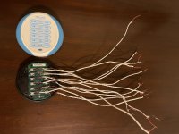
So I had a different approach to upgrade my system for iPhone remote control... I have an poolside remote (AQL-SS-RF)that I took apart to see if it could be used. You press the buttons on the remote and it’s a momentary (inching) contact that executes the command through the modbus antennae connected to the main control board. Using a multimeter I determined that depressing the switch closed the top contacts of the switch with the bottom contacts. So my idea was to solder Wi-Fi relays in parallel with these switches so I could control each command.
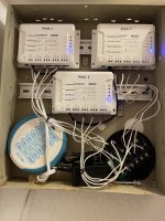
I needed 12 inching channels to control all the functions on the remote and therefore I used three 4CH Sonoff Wi-Fi relay boards.

 sonoff.tech
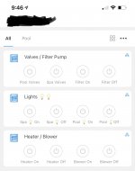
In taking this approach, I gave up use of the actual remote since I have to keep it stationary in the panel. But I can now control the pool from our iPhones and Alexa. I'm including a picture of the eWeLink interface which allows me to control the valves, pump, lights, heater and blower.
Definitely improved my soldering skills 100x on this project. I would caution that if you follow this method, you taking a risk when you begin soldering on the circuit board. The board has circuits on top and bottom and you need to be very careful with you solder not to mistakenly connect any points together besides bypassing the switches.
For this project, I had everything needed except the Sonoff units and DIN rails, so this project came in at ~$115 total.
All works well, and happy with it. Perhaps this approach might help someone else.
Take Care,
Mike
Since we moved in our house back in 2013, I’ve wanted to control my vintage Hayward Goldline pool automation from my iPhone and Alexa.
All the experts I talked to told me my current main control board (AQL-PS-8-X295) could not integrate with hardware to operate pool from my phone. I'd have to replace the main Hayward control board to the GLX-PCB-PRO version and then buy a new AQL2-BASE-RF antennae, Aqua-Connect, etc. and it was well over $1k, which I was not willing to spend.
I dug into the reasoning behind why it’s so complicated and with my Hayward Goldline system, they use RS485 modbus comm protocol between the remote antennae or any wired remote control modules. A couple of very smart guys online have deciphered the messaging code but it appears very poorly written and difficult to manage. I could have purchased a RS485 comm adapter and completed the programming but this would be stretching my abilities and seemed to be a challenge for those attempting it.
So I had a different approach to upgrade my system for iPhone remote control... I have an poolside remote (AQL-SS-RF)that I took apart to see if it could be used. You press the buttons on the remote and it’s a momentary (inching) contact that executes the command through the modbus antennae connected to the main control board. Using a multimeter I determined that depressing the switch closed the top contacts of the switch with the bottom contacts. So my idea was to solder Wi-Fi relays in parallel with these switches so I could control each command.
I needed 12 inching channels to control all the functions on the remote and therefore I used three 4CH Sonoff Wi-Fi relay boards.
SONOFF 4CHR3/PROR3 - 4 gang 433Mhz RF remote WiFi smart switch
SONOFF 4CHR3 4CHPROR3 is a 4 gang 433Mhz RF remote WiFi smart switch that supports to control 4 appliances.
sonoff.tech
In taking this approach, I gave up use of the actual remote since I have to keep it stationary in the panel. But I can now control the pool from our iPhones and Alexa. I'm including a picture of the eWeLink interface which allows me to control the valves, pump, lights, heater and blower.
Definitely improved my soldering skills 100x on this project. I would caution that if you follow this method, you taking a risk when you begin soldering on the circuit board. The board has circuits on top and bottom and you need to be very careful with you solder not to mistakenly connect any points together besides bypassing the switches.
For this project, I had everything needed except the Sonoff units and DIN rails, so this project came in at ~$115 total.
All works well, and happy with it. Perhaps this approach might help someone else.
Take Care,
Mike
Attachments
Last edited:
