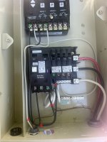
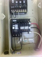
GFCI breaker tripping using Intermatic P1353ME timer
- Thread starter JGard911
- Start date
You are using an out of date browser. It may not display this or other websites correctly.
You should upgrade or use an alternative browser.
You should upgrade or use an alternative browser.
911,
When you get power from a GFCI breaker, the neutral wire has to go back to the breaker and not to the neutral bus bar.
Thanks,
Jim R.
When you get power from a GFCI breaker, the neutral wire has to go back to the breaker and not to the neutral bus bar.
Thanks,
Jim R.
911,
Does your pump run off of 240 VAC or 120 VAC?
It is hard for me to see where each black wire is going so tell me more.
1. Where does the black wire on the left side of the GFCI breaker go?
2. Where does the black wire on the right side of the GFCI breaker go?
3. Where does the black wire on the open 15 amp breaker go?
Thanks,
Jim R.
If that is a 120v installation, you have created a dead short at CIRCUIT 1. And, you can't run a 120v load on a double-pole GFCI breaker. It senses an unbalanced load (which indicates a "ground fault"). If it is 240v white wire shouldn't be used.
Last edited:
- Jul 21, 2013
- 52,486
- Pool Size
- 35000
- Surface
- Plaster
- Chlorine
- Salt Water Generator
- SWG Type
- Pentair Intellichlor IC-60
You can run a 120V load off one leg of a 240V GFCI CB. The neutral for the 120V loads need to connect to that middle screw on the CB.If that is a 120v installation, you have created a dead short at CIRCUIT 1. And, you can't run a 120v load on a double-pole GFCI breaker. It senses an unbalanced load (which indicates a "ground fault"). If it is 240v white wire shouldn't be used.
Never worked that way for me.You can run a 120V load off one leg of a 240V GFCI CB. The neutral for the 120V loads need to connect to that middle screw on the CB.
Never worked that way for me.
Kind of the whole point of having a neutral connection on a GFCI breaker. It certainly won't work if you try to steal 120 volts from a 240 GFCI breaker without connecting the 120's neutral back to the breaker.
Not that it matters, as it appears that the OP has lost interest.
Thanks,
Jim R.
- Jul 21, 2013
- 52,486
- Pool Size
- 35000
- Surface
- Plaster
- Chlorine
- Salt Water Generator
- SWG Type
- Pentair Intellichlor IC-60
Welcome to TFP.
IF YOUR PUMP IS 120v then I believe this is the correct wiring...
Wire C on screw 5 goes to screw 6 - that is a hot 120V wire to power the timer.
Wire B goes to screw 2 - that is the LOAD hot wire
Wire A goes to screw 3 - that is the load neutral connection
Wire D goes from screw 4 to screw 1 - that is the LINE hot 120v wire.
The black wire on the unused left hand screw on the CB should be removed.
Now why are you using half of a 240V GFCI CB for a 120V pump?

Thread Status
Hello , This thread has been inactive for over 60 days. New postings here are unlikely to be seen or responded to by other members. For better visibility, consider Starting A New Thread.


