GFCI Breaker for Main Pump Test Button Doesn't Work

I'm referring to the pump motor.
My understanding of Timers is they are either 120 or 230. But cannot be made to do both.
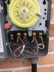
A 120V timer switches one hot wire.

A 240V timer should switch both hot wirse according to code. You see some 240V circuits being switched by one hot wire which is against code.

A 240V timer with a 120V clock can be used to switch the one hot wire on a 120V circuit.

A 120V timer cannot be used to switch a 240V circuit and meet code.
 
Last edited:
  • Like
Reactions: borjis
The current timer has a 120 volt clock.

So the clock needs 120 volts from terminal 1 and A. Terminal A should be connected to neutral.

The timer is double pole. So, it can do both legs of a 240 volt load or 2 separate 120 volt loads.
 
Last edited:
  • Like
Reactions: borjis
Both existing motors are 120/230. Based on what I now understand, the main pump is hooked to 120, the backup to 240.

IMG-3898.JPG

perhaps its a little hard to tell, but the main pump black wire is connected to #2, main pump white wire connected to #4, and the bare copper wire is connected to the green ground coming from the breaker, as well as being wrapped around a grounding screw, which is hidden behind the red twist on cap.

Would there be any advantage to switching my current main pump to 240v?
 
Since you have 240 available, that's the preferred way to do it.

Here's what you should have:
One red wire from one of the breaker "Load Power" terminals to the timer #1 terminal.

One red wire from the other "Load Power" terminal on the breaker to the timer #3 terminal.

One white wire from the breaker "Load Neutral" terminal to the timer "A" terminal.

The clock wires connected to terminals "A" and #1.

The wires going to the pump connected to timer terminals #2 and #4.

The pump selector set to 230 volts.

So, the changes are:

Move the red wire from "Load Neutral" to "Load Power".

Install a white wire from "Load Neutral" to timer "A".

Move timer clock wire from terminal #3 to "A".

Change pump selector to 230 volts.
 
Both existing motors are 120/230. Based on what I now understand, the main pump is hooked to 120, the backup to 240.

View attachment 115957

perhaps its a little hard to tell, but the main pump black wire is connected to #2, main pump white wire connected to #4, and the bare copper wire is connected to the green ground coming from the breaker, as well as being wrapped around a grounding screw, which is hidden behind the red twist on cap.

Would there be any advantage to switching my current main pump to 240v?


This timer looks like it is 240V for load and clock.

Line in is two red hot wires plus one ground.

Load is a black hot wire on terminal 2 and a white hot wire with black electrical tape around it indicating it is a hot wire on terminal 4.

Clock is connected to 240V power in 1 & 3.

Put a voltmeter on 1 & 3 and measure the voltage.
 
One of the red wires is currently connected to the Neutral terminal of the breaker.

So, the clock and pump are getting 120 volts.

The label on the timer says that the clock is 120 volts. Unless the clock has been replaced, it should be 120 volts.

One of the red wires has some duct tape on it. I'm guessing that it might be an attempt to identify it as the neutral.
 
Last edited:
One of the red wires is currently connected to the Neutral terminal of the breaker.

So, the clock and pump are getting 120 volts.

The label on the timer says that the clock is 120 volts. Unless the clock has been replaced, it should be 120 volts.

One of the red wires has some duct tape on it. I'm guessing that it might be an attempt to identify it as the neutral.


Ok, I didn't see the breaker box side of the wires. I hate when the wrong color wires are used. Duct tape on the red wire; black tape on the white wire just creates confusion.

I see now. They took a 240V circuit and moved a red hot wire to the neutral on the 240V CB to make it a 120V circuit.

Never mind.
 
Awesome. Thanks so much James. I have learned a ton about electricity just from this thread. I wish I had known all this 18 months ago when I sent that 2-speed pump back, and got another crappy one-speed. Or I wish the people at the place I bought it had said "it's not hard to wire it for 240v, you should keep it."

One last thing - when I go shopping for wire, what should I get? Is there a specific gauge or should I just replace all of it? Is there a name for the 3 wires all bundled together?
 

Enjoying this content?

Support TFP with a donation.

Give Support
I would use 12 AWG THHN. You can buy it at Lowe's or Home Depot by the foot.

All you really need is a couple of feet of white wire to go from the breaker "Load Neutral" to "A" in the timer.

The rest of the wires should be fine.

You can clean up the ends of the wire by cutting off the ends and restripping the ends if you want or you can replace the wires if you think that it's necessary.

Buy a wire stripper when you get the wire.

If you want to replace the power wires, get 12 AWG THHN in black and red.

Buy individual wires. No Romex or wire combinations.
 
  • Like
Reactions: MyAZPool
Thread Status
Hello , This thread has been inactive for over 60 days. New postings here are unlikely to be seen or responded to by other members. For better visibility, consider Starting A New Thread.