Failed timer, should manual switch still work?

brew4eagle

Well-known member
Jun 2, 2016
48
Stafford, VA
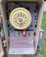
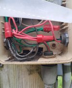
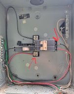
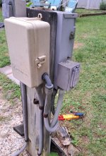
I have power getting to the pool timer, however the motor gears are not turning. Tried to help them move via the gear sight window and still nothing.

When I flip the manual switch no power is going to the pump. Will a failed timer mechanism prevent the manual switch from providing power to the pump?
 
What model timer?

Depends what in the timer failed.

Pictures?
 
Do you have a multimeter?

Turn off the CB to the timer.

Use the continuity setting or OHMS setting and test between LINE1 to LOAD2 screws and LINE3 to LOAD4 screws. See if you have continuity when you throw the manual level on.

Either way you need to replace the mechanism.
 
Do you have a multimeter?

Turn off the CB to the timer.

Use the continuity setting or OHMS setting and test between LINE1 to LOAD2 screws and LINE3 to LOAD4 screws. See if you have continuity when you throw the manual level on.

Either way you need to replace the mechanism.
Yes, continuity on both. So I assume that means the pump should get power with the manual switch?
 
Last edited:
No continuity when switch is off, continuity when switch is on. So if I'm following, that means pump should be able to be turned on with the switch, correct?
Correct.

Is there 240V at L1 and L2 at the pump?
 

Enjoying this content?

Support TFP with a donation.

Give Support
With power to the timer and the manual switch off I see about 100V between Line 3 and Load 4, which goes to pump in question. With switch on I see 0V. Not sure if that is useful info though

That is correct you are testing one hot leg of a 240V circuit.

With switch on you see 0V because there is no voltage differential between the sides of the switch.

Do you understand what you are testing or just poking around?

Is there 240V at L1 and L2 at the pump?
 
That is correct you are testing one hot leg of a 240V circuit.

With switch on you see 0V because there is no voltage differential between the sides of the switch.

Do you understand what you are testing or just poking around?

Is there 240V at L1 and L2 at the pump?
I do not. Can I test for 240V at 'L1 and L2 at the pump' from the timer box? Do I check incoming V to timer for 240 across Line 1 and Line 3, then with switch on check for 240 V to pump via Load 2 and Load 4?
 
Last edited:
I do not. Can I test for 240V at 'L1 and L2 at the pump' from the timer box?

No, you need to open up the wiring box in the back of the pump and test voltage between where the wires connect to.
 
  • Like
Reactions: brew4eagle
Yes.


And you should see 240V between the LOAD screws with the lever in the ON position.
Got it. So I see 240V at the breaker behind the timer when I turn that breaker on. I do NOT see 240V across Line 1 and Line 3 at the Timer, I see 0 V. Likewise see 0V across Load 2 and Load 4 with switch on.

I do have a new timer in hand, any chance swapping that in is a logical step?
 
Show me where this breaker is behind the timer you are testing.

If you have no power at L1 and L3 then the timer is not powered and will not run. That is not a broken timer. That is a CB problem or wiring problem feeding the timer.
 
Show me where this breaker is behind the timer you are testing.

If you have no power at L1 and L3 then the timer is not powered and will not run. That is not a broken timer. That is a CB problem or wiring problem feeding the timer.
I have 240V with switch on when check where I drew arrows
 

Attachments

  • Screenshot_20240517_165332_Gallery.jpg
    Screenshot_20240517_165332_Gallery.jpg
    167.9 KB · Views: 5
  • Screenshot_20240517_165401_Gallery.jpg
    Screenshot_20240517_165401_Gallery.jpg
    273.3 KB · Views: 5
You need to test at the contact screws for the CB circled in green...

1715979635117.png
 

Enjoying this content?

Support TFP with a donation.

Give Support