Electrical Stuff

R

ralphsyv

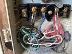
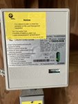
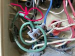
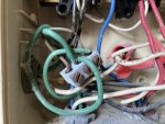
I'm trying to figure out the electrical stuff. This is inside the Intermatic 104P timer, which I think is supposed to be 240v. The pump can be wired 240v or 115v. I think power comes from the black wires and red goes to the pump. The blue wire doesn't make sense - looks like it's not connected to anything? We have a plan with (Florida Power + Light) that is supposed to shut off power to the pool pump in high demand periods - looks like the blue wire is connected to that device, but it's not actually wired to the pump? IMG_0729.jpegIMG_0727.jpeg
 
Ralph,

Back up and show us a couple of pics of the whole set up..

Currently that timer is only controlling the voltage on the blue wire..

I "assume" the power company's box is actually controlling your pump.. I suspect that the timer puts power on the blue wire which closes a relay in the power company's box. When the relay closes your pump turns on.. When the power company wants to shed loads, they tell their box to not turn on the relay that controls your pump.

Thanks,

Jim R.
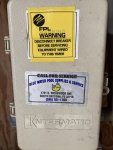
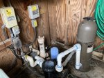
Here's the whole setup. We have these devices from the power company for the air conditioner, water heater and pool pump and save $80/month on our electric bill so they can cut off power during high demand periods. Right under the Intermatic timer is a switch to disconnect power to the pool pump, connected to the pump from there... I'm not sure if the pump is on 240 or 115 volts. The light inside the shed is wired into it too, which is 115 volts. The plastic thing to the left under the timer is a 115v GFI outlet and has no power and doesn't work.IMG_0316.jpeg
 
Ralph,

Thanks for the pics...

I think my initial guess is about right.. But the only way to know for sure is to use a meter and check voltages.

So.. What is it that you are trying to do? What is your question? What does not work?

Thanks,

Jim R.
 
If you want help understanding the wiring you need to move the ground block with the green wires and the wire nut with the white wires out of the way so we can see each wire coming in from the four conduits and where it connects to.

The left conduit is the power feed. I see where the black p, white, and green wires go. It looks like there is a yellow wire that disappears in the back.

Similar the other wires are hidden behind the ground block and neutral white wire nut. Let us see where all the wires go.
 
@Jimrahbe and @ajw22 -Thanks for your help. I don't have a meter, I wish I brought one back with me from Chicago. There's a transformer on the outside for the pool light that doesn't work, but it's not a high priority right now.

The pump works right now. The timer is set to turn on at 8 am and off at 4pm and that works.

One of the green grounding wires attached to the grounding block is burned/damaged. So I'm kind of concerned about that.

That plastic cover below the timer has an outlet with a transformer plugged in for outdoor lighting - it doesn't work. That's also not a high priority right now.
 
Which ground wire concerns you? I see 3 green wires and two bare wires connecting in the block. All of them look functional to me.
 
@ajw22 I'll post another photo tomorrow. The bare wire in the right terminal is damaged and burned. I think there was a lightning strike around 5 years ago so that might have caused it. I don't know.
 

Enjoying this content?

Support TFP with a donation.

Give Support
Yup, I noticed that and thought the wire may have been nicked during wiring. I Would just cut the wire at the nick and reattach it to a screw in the ground block.

Lots of things in and around the box look like they can use a cleanup. Once you begin digging into the wiring it may be better to redo it all.
 
Ralph,

Thanks for the pics...

I think my initial guess is about right.. But the only way to know for sure is to use a meter and check voltages.

So.. What is it that you are trying to do? What is your question? What does not work?

Thanks,

Jim R.
Right now, I'm just trying to make sure it's safe and wired correctly. It looks like you're right. I think the blue wire is the load to the pump and normally the other wire from the pump would go to terminal 4, but in this case goes through the FPL load management box. I'm going to fix that burned ground wire.
 
Yup, I noticed that and thought the wire may have been nicked during wiring. I Would just cut the wire at the nick and reattach it to a screw in the ground block.

Lots of things in and around the box look like they can use a cleanup. Once you begin digging into the wiring it may be better to redo it all.
Good idea. there's still enough wire to cut it and reattach, but I probably should replace the wires.
 
Thread Status
Hello , This thread has been inactive for over 60 days. New postings here are unlikely to be seen or responded to by other members. For better visibility, consider Starting A New Thread.