Electrical connection for Hayward Aquarite and Intermatic Digital Timer

hgiljr

0
Jul 13, 2015
94
Miami, Fl
Pool Size
12000
Surface
Plaster
Chlorine
Salt Water Generator
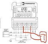
Hello everyone. I am trying to figure out the proper electrical connection in order for the SWG to work in both low and high pump speeds. It currently only turns on with in high speed. My pool timer is the intermatic P1403 and it is currently wired as follows:
Terminal 1 = Hot wire coming from main breaker and a jumper from Terminal 1 to Terminal 3
Terminal 2 = Hot wire coming from main breaker and a jumper from Terminal 2 to Terminal 7
Terminal 3 (Labeled NO-1) = Jumper from Terminal 1 and a jumper from Terminal 3 to Terminal 5
Terminal 4 (Labeled COM 1) = Blue cable coming from pump and black cabled coming from SWG
Terminal 5 (Labeled NO-2) = Jumper from terminal 3
Terminal 6 (Labeled COM 2) = Black cable coming from pump
Terminal 7 (Labeled NO-3) = Jumper from Terminal 2 and second black cable coming from SWG
Terminal 8 (Labeled COM 3) = Red cable coming from pump
Terminal 9 (Labeled NO-4) = This is AUX and is empty
Terminal 10 (Labeled COM 4)= This is AUX and is empty

Yesterday I tested the following:
1. Placed the black cable from SWG that was going into COM 1 over AC terminal 1Screen Shot 2021-09-30 at 9.36.08 AM.png
2. I moved second cable from SWG that was on No-3 over to Aux com 4.
3. I placed a jumper from AC Terminal 2 over to Terminal 9 No-4. This allowed for SWG to work in low and high. The only thing I didn’t like is that when SWG control box turned on it had a hard start noise. I decided to move all cables back how they were. Not sure if that’s a normal noise but it did work in both speed.

My goal is to get the SWG working in both speeds. The SWG control box is set for 240. Any recommendations on how to achieve this, let me know. Thank you
 
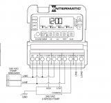
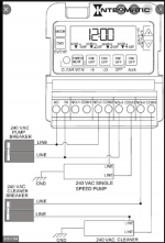
Hey there, can you take a pic of the wiring? I think you should be looking at the dual speed wiring diagram. From the diagram I’m not really seeing a way to break line 1-2 and loading them simultaneously. It would act more like a kill switch breaking just one of the hots. So it would be best not to go off what I say alone. Here is the dual speed diagram.
1633107501519.jpeg
But I’ll wait for the pictures trying to figure out what goes where from the text, I would have to draw it out. @ajw22 maybe Allen has some knowledge.
 
I don’t really see an option that I would be comfortable with setting it up to run for both and high/low speeds. You could hook it up to the aux and run it within the scheduled parameters. Or just hook it up to the low speed since it will be running the longest. Edit: but would still only break one leg of the 220v circuit(if high clicked on while it was hooked to low). I don’t know if there is adverse effects or not.
 
Last edited:
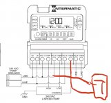
1633119382804.jpeg
T being swg you hook up one leg to the line side and second leg on load side of the common relay. So again I don’t know if it’s bad practice to break only one leg in a 220v circuit or not. Most circumstances both are broken in relay. So hopefully someone will come along and enlighten.
This is also based on your wiring being the same as the diagram provided.
 
View attachment 375317
T being swg you hook up one leg to the line side and second leg on load side of the common relay. So again I don’t know if it’s bad practice to break only one leg in a 220v circuit or not. Most circumstances both are broken in relay. So hopefully someone will come along and enlighten.
This is also based on your wiring being the same as the diagram provided.

That should work.

I would put a warning label on the SWG saying "WARNING ONE LINE IS HOT WITH TIMER OFF!"
 
Last edited:
  • Like
Reactions: Poolbreh
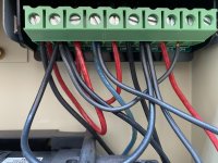
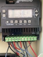
Here pics of the actual connections. I have no problem moving SWG to AUX and setting the parameters to run during the hours that the pump is set to run, but in testing it yesterday when I tested the following below and decided to put everything back.
1. Placed the black cable from SWG that was going into COM 1 over AC terminal 1
2. I moved second cable from SWG that was on No-3 over to Aux com 4.
3. I placed a jumper from AC Terminal 2 over to Terminal 9 No-4. This allowed for SWG to work in low and high. The only thing I didn’t like is that when SWG control box turned on it had a hard start noise. I decided to move all cables back how they were. Not sure if that’s a normal noise but it did work in both speed.

If someone knows the proper way to hook up into AUX, then I can try it out and program accordingly. Thanks againIMG_6462.jpgIMG_6461.jpg
 
Yea that would be my concern someone going in and thinking it was off but one leg being live. I wasn’t sure if it would hurt anything breaking one leg of a 220v circuit

A SWG connected to a CB would have both wires always hot.

It will not hurt anything but most people and sloppy electricians may assume both wires are not hot when the device look unpowered. The experienced electricians never assume a wire is not powered and always test it before touching it.
 
  • Like
Reactions: Poolbreh
The manual doesn’t really specify right or wrong ways of hooking up swg to your particular system. The way you you had it setup to the aux sounds like it would work, but it’s still only breaking one leg of the circuit which is fine. The way I’ve shown it will power on(breaking one leg) but will power on whenever the pump turns on high/low. As for the aqua rites I do recall the make an thud noise when power is reset.1633122798725.jpeg
 

Enjoying this content?

Support TFP with a donation.

Give Support
And yes it looks like your wiring is hooked up like the diagram. But I would just verify before doing anything.
Actually it’s different then your diagram. It’s going to Com 1 and No3 vs your diagram which is No2 and com 3. I will look into your diagram tomorrow and see the results. Thank you everyone.
 
The diagram won’t show how you have the swg hooked up. Its for reference, what’s important is your wiring for lines and loads line up with diagram and from the picture it appears so. The way you describe the swg was previously hooked up would work on high speed(having one leg break by high speed relay, the second leg constantly having power) the diagram above shows it similar concept. But we are breaking one leg of the circuit using the common, because the common will be used for high/low speed while the second leg will have constant power. The way two speeds work high or low power the pump and common. It’s designed only to power either high or either low not at the same time otherwise it will damage the pump. So you want to tie into the load side of the common and have the second leg powered.
 
To do this you would hook swg up to no2 and com3
So this works and allows for the SWG to run in low and high. Now I still get the large thump sound when the SWG starts up while in low but no thump sound when it starts up in high. If I start the pump in high and switch to low, there is no thump sound. In in south Florida. Does it matter if I start the pump in the morning in high for 4 hours and then have it switch to low in the afternoon for another 4 hrs?

Normally my schedule has always been to start in low and then high but if it has to be reversed to avoid this thump sound I can do it.
Thanks again for all your help.
 
unfortunately I couldn’t tell you what the thump is from, I always associated with the transformer being energized. I do recall hearing it with the aquarites when power was cut off and restored, so I have heard it before. But there is no harm and changing the schedule to reduce the thump if that’s your preference.
 
Thread Status
Hello , This thread has been inactive for over 60 days. New postings here are unlikely to be seen or responded to by other members. For better visibility, consider Starting A New Thread.