Easytouch no longer controlling Intelliflo

ft,

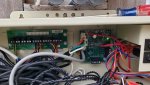
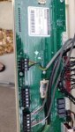
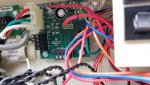
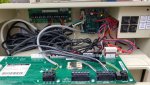
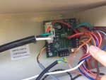
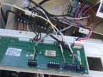
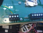
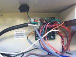
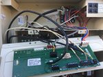
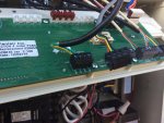
The EasyTouch has one com port, but several com connectors that are all electrically the same. The SWCG board must be connected to J20 otherwise you will not be able to control your SWCG. The IntelliFlo can also be connected to J20 or any of the three com ports on the SWCG board.

I guess the SWCG card could be intermittnetly bad, but I doubt it.. More likely a bad connection.

Thanks,

Jim R.
 
There are 4 Com wires. Red, black, yellow and green.

Red pin 4 (+15 VDC)
Black pin 1 (ground)
Yellow pin 3 (+ data)
Green pin 2 (- data)

Only yellow and green should be used for the Intelliflo Com wiring.

If red and black were used, that might have caused an issue.

If the yellow and green were reversed, that would cause a problem.

It might have been a bad connection or maybe a bad wire.
 
Yes, the Intelliflo pump is working. The pump has been connected as shown since yesterday. According to Jay (Pool Maintenance) the pump was previously connected to the smaller board located behind the main board. When connected in that way, the pump was not working. I am passing on what he told me so I apologize if my explanation is falling short.

If you take a look at the smaller pcba (not sure about exact name), you can see a connector that was disconnected. Jay told me he disconnected the pump from the pcba board and, instead, wired it directly to the main board comport.

He did this in order to isolate the pcba board and see if the pump worked if it was connected directly to the main board, which it does.

Does this make sense?
 
Okay, now I think I am understanding the comments about the red black yellow and green wires. I posted a picture showing all four wires connected to the SWCG board and another picture showing the Intelliflo green and yellow wires attached to com 1 on the main board. I will post again below.
 

Attachments

  • 43DF3C29-CEC1-433E-8A7B-FD659E58C159.jpeg
    43DF3C29-CEC1-433E-8A7B-FD659E58C159.jpeg
    395.5 KB · Views: 2
  • 5AD457A6-8A71-4FAB-BE6E-C19AAFCFECDC.jpeg
    5AD457A6-8A71-4FAB-BE6E-C19AAFCFECDC.jpeg
    322.8 KB · Views: 3
Today I am going to try and hook everything back up correctly so I can get everything working again. I need a little help regarding the gray jumper wire (see photo). One end is connected to the left lower side of the small pcba board and the other end is hanging loose. Do I pull the screw terminal block off the J20 and replace it with the one coming from the previously mentioned pcba board?

If I do that do I connect the green and yellow wires from the Intelliflo pump to the J20? If so, it looks like I would be doubling up with the green and yellow jumper wires.

As a side note I checked for loose connections and discovered that the connection block on the lower right side wants to lift up off the 4 circuit board pins. I pushed it back tight to the board, but when I checked after a few minutes it creeped back off the board again. That could be one of my problems.
 

Attachments

  • C602A5E9-E681-4F6F-B05D-D07C3484BA9B.jpeg
    C602A5E9-E681-4F6F-B05D-D07C3484BA9B.jpeg
    436.9 KB · Views: 3
  • 667E9E98-7238-4A79-846B-7F14E5F88151.jpeg
    667E9E98-7238-4A79-846B-7F14E5F88151.jpeg
    406.4 KB · Views: 3

Enjoying this content?

Support TFP with a donation.

Give Support
FT,

I suggest that you read post # 21 again..

The grey wire connects the J20 com port to the SWCG board mounted on the back wall of your EasyTouch. You do not need an expansion module as that is once of the functions of the SWCG board.. it has three com ports.. If it were physically possible, you could connect all the wires to J20.. But since you can't cram all the wires into one plug, the three extra com ports on the SWCG give you more places to connect.

Thanks,

Jim R.
 
Let me know if you have questions. - yeah, the extension board was for the indoor control panel and the screenlogic controllers... sorry, been a few years since I hooked it up. :)
 

Attachments

  • 20200425_080731.jpg
    20200425_080731.jpg
    48.2 KB · Views: 5
  • 20200425_080723.jpg
    20200425_080723.jpg
    30.9 KB · Views: 6
  • 20200425_080629.jpg
    20200425_080629.jpg
    30.5 KB · Views: 7
  • 20200425_080622.jpg
    20200425_080622.jpg
    23.5 KB · Views: 7
  • 20200425_080755.jpg
    20200425_080755.jpg
    43.8 KB · Views: 6
  • 20200425_080840.jpg
    20200425_080840.jpg
    55.1 KB · Views: 6
Okay Jim, I have everything connected as described in post 21. Just to make sure, would you take a look at the pics and confirm. I connected the Intelliflo pump to the bottom com port on the SWCG board. Thanks!
 

Attachments

  • C5753723-6BAE-4723-8CF3-893D21DC589F.jpeg
    C5753723-6BAE-4723-8CF3-893D21DC589F.jpeg
    314.1 KB · Views: 6
  • 11311647-7BBD-4691-A134-2FDE987C9228.jpeg
    11311647-7BBD-4691-A134-2FDE987C9228.jpeg
    482.5 KB · Views: 6
FT,

Well.. You already have a com port expansion module.. So you have all kinds of places to connect to your com port.. All of them are electrically the same, so it does not matter what goes where.. the only thing to remember is that they all must be connected together.. It does not matter if J20 is connected the SWCG board and the SWCG board is connected to the expansion board or if J20 is connected to the expansion board and then the expansion board is connected to the SWCG board..

Thanks for the pics.. I had never seen an expansion board before.. :goodjob:

Thanks,

Jim R.
 
Okay, I had everything connected as shown in post 34. I flipped the breaker for the panel, heard the pump relay click, but the pump did not turn on.

I also tried connecting the pump to the J20 com port, doubling up on the yellow and green wires coming from the swg/expansion board. No luck with that setup either.

I then disconnected the jumper from the SWG/expansion board and went back to connecting the Intelliflo pump directly to the J20 com port and the pump turns on with no problem. Any ideas on what I should try next?
 
FT,

One of the connections is loading down the comm bus.. You will have to figure out which one. Obviously, it is not the pump, because it works when nothing else is on the bus.

If this were my system, I would isolate the expansion module and the SWCG board.. I would run the cable from J20 to the SWCG card. I would connect nothing to the SWCG card but the pump and see what happens. If it works, then you know the problem is with one of the other connections.. If it does not work, you know that the SWCG card is bad.

Unfortunately, you should not be connecting or disconnecting things from the com port with the system running, so this could be a pain.

Thanks,

Jim R.
 
I thought I would try something. I removed the terminal block from one of the SWG com ports located on right side of SWG board. The wired remote and screenlogic were connected to this com port. See picture below. Now the pump works fine when connected to one of the SWG com ports. I’m getting there. I am now going to reconnect the two removed devices, one at a time, and see if I can narrrow the problem down.

Jack
 

Attachments

  • 21454030-EB2A-4DF0-8291-5FF3691D3E3B.jpeg
    21454030-EB2A-4DF0-8291-5FF3691D3E3B.jpeg
    314.1 KB · Views: 5
Some devices use all 4 wires and some use only the two data wires.

Check the manual to make sure that you're not connecting the red and black wires when you shouldn't be.

I'm not sure but if the red wire is powered from both ends, it might be neutralizing the voltage.
 

Enjoying this content?

Support TFP with a donation.

Give Support
Thread Status
Hello , This thread has been inactive for over 60 days. New postings here are unlikely to be seen or responded to by other members. For better visibility, consider Starting A New Thread.