DIY Automation/Control ESP32

CNYLovin

Member
Jan 19, 2021
10
NY
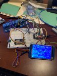
I have created a proof of concept using an ESP32 and Arduino code to control 8 relays. I have a single speed waterway plastics pump, Hayward heater, 3 intermatic valves and two lights (landscape and pool). I have various power needs to control everything 120v, 24v AC and 5V DC. I already have high amp relays as well.

I’ve seen a few threads using DIN rails/power but I’m not as familiar with this nor know if this is appropriate for my application.

Does anyone have any recommendations on the best way to approach this?432C7286-2D3B-4106-83E8-E585A190B806.jpeg
 
Din rails are used for mounting your components in a box. Lots of us here use Din rail mounted components just because it is easier to work with with and looks cleaner. You can check my build thread in my signature.

Ask questions and make sure you post what you are doing. We all like to learn from people around here.
 
  • Like
Reactions: CA_Tallguy
I have been looking at the Atlas Scientific stuff. They have a good layout for a DIY PH doser using arduino. They even sell a pool specific setup. It's more for monitoring, but I think someone can se the data to make an auduino spit out acid or chlorine.
 
A bunch of us around here use the Atlas Scientific stuff. I have their industrial pH probe which seems to work fairly well. @MyAZPool has taken it to a new level. You might want to check out his posts.

Most of us are using Raspberry Pi, but that is primarily because we want to integrate with NodeJS-PoolController for managing Pentair RS-485 based products.

For acid or chlorine dosing, that is simply turning a relay on and off on a dosing system. Stenner is very popular around here for that. I was about to build that into my build but I have discovered with my pH probe that my pH is far more stable than I thought before and my dosing is now down to about once a week.
 
@CNYLovin and @Summoner12
Regarding DIN Rail mounting of components, the Atlas Scientific line and other DIY pool automation projects, you may want to check out the following threads.
Hoping you will find some useful information to assist in your future DIY pool automation, sensor and chemical control endeavors.
r.

 
Last edited:
  • Like
Reactions: CA_Tallguy
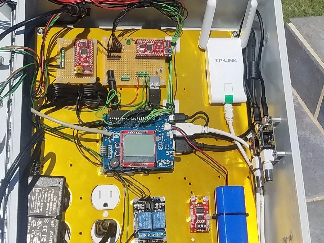
CNY, I’ll add my project to that list although I’ve been dormant most of this last year.


The RaspberryPi guys have created a lot awesome of projects and building blocks that makes a DIY pool controller much more accessible. You are early enough in your development that you might consider a course change. Make sure to look at all the documentation detailed and collected by @MyAZPool. There is a lot of work done by a bunch of smart people. I’m definitely jealous of those with an Intellicenter that can take full advantage. For those of us without an intellicenter, it still might make sense. I will consider it in the future, but I’m currently having too much fun with my current path as I am sure you are, haha.

I think you will find that actually deploying the system is difficult, especially since, for many, it is a project that never ends. Dividing it into pieces and building up the blocks is probably a necessity. When and how do you make it permanent? Do you have a way to develop & test code remotely for ESP32? Are you leaning towards breadboarding/soldering/din’ing? These projects can suck up as much time as you have.

Congrats on your progress so far! and keep asking questions and giving updates.
 
Last edited:
  • Like
Reactions: MyAZPool
There is no reason a RPi can't talk with an ESP32. I think doing low level IO is actually much easier on an Arduino based device as they run without an OS and are a lot closer to "real time". But the RPI can still be used to interface open source "pool automation" code to other processors.

It looks like a fun project, something I likely would tackle if I had more time. With the pool stuff, the less automation I use the better, though for me. I guess that is my one manual thing around the house and I would like to keep it that way. But I am pretty good at these sort of projects and I hope to follow what you are doing.
 
  • Like
Reactions: jonpcar
CNY, I’ll add my project to that list although I’ve been dormant most of this last year.


The RaspberryPi guys have created a lot awesome of projects and building blocks that makes a DIY pool controller much more accessible. You are early enough in your development that you might consider a course change. Make sure to look at all the documentation detailed and collected by @MyAZPool. There is a lot of work done by a bunch of smart people. I’m definitely jealous of those with an Intellicenter that can take full advantage. For those of us without an intellicenter, it still might make sense. I will consider it in the future, but I’m currently having too much fun with my current path as I am sure you are, haha.

I think you will find that actually deploying the system is difficult, especially since, for many, it is a project that never ends. Dividing it into pieces and building up the blocks is probably a necessity. When and how do you make it permanent? Do you have a way to develop & test code remotely for ESP32? Are you leaning towards breadboarding/soldering/din’ing? These projects can suck up as much time as you have.

Congrats on your progress so far! and keep asking questions and giving updates.
Hi @jonpcar
Hey, thanks for including your thread to the list. Any comprehensive list of pool DIY projects should definitely include it and frankly I thought I had.
I've corrected my mistake above and in my hardware thread as well. :thumleft:
Thanks again and take care....
r.
 
  • Like
Reactions: jonpcar

Enjoying this content?

Support TFP with a donation.

Give Support
I use an ESP8266 to control my pool equipment with relays. I have a pi inside that tells the ESP what to do. They talk over MQTT. Actually have a couple pi's, one runs Home Assistant and the other one is running Node Red.

Using Pi's and readily available software like this, its easy to make a reasonable web based user interface, then use your phone or tablet or PC to control things. You can also have timers in the Pi's to run the pumps every day.

So use the ESP32 to control the relays, and then consider adding a pi.
I'm lazy, so I used ESPeasy to implement the ESP so it can talk over MQTT. Tasmota works too, and there are other options.
Then add Mosquitto or some other MQTT broker on the pi.
I have a bunch of ESP's around the house for different chores, all talking MQTT

Randy
 
To wire up my ESP's, I used double or triple bases for the mini D1's
link to bases from ali (I bought from a different store, just found this link in a quick search)

But I don't see bases like that for the ESP32. Too bad, it really helped me.
I always install a set of sockets in the base, so I can plug the ESP into the base, and remove if I need to.
Recently I had one fail, and it was easy to remove/replace and get my pool up quickly.
 
@randytsuch , both you and @Rattus Suffocatus describe using a RaspberryPi to control and/or monitor the microcontroller. Have you documented your project anywhere? I haven’t looked into a master/slave configuration at all but it sounds like a possibly elegant, future solution for me, as well as for the OP. Do the ESP32 and your ESP8266 connect over a wifi network to communicate with the RPi?

Is it possible to have an RPi out at the pool equipment pad directly connected to the ESP/microcontroller via serial ports, or some other communications method? It sure would be fun to take advantage of some of these awesome projects being developed for the RPi.

CNY, Randy is right about using sockets...and adding headers everywhere...unless you stay on a breadboard, of course. I have seen some projects do that. It doesn’t look permanent, haha.
 
To expand further into the details of my project. I leverage home assistant, MQTT message and NodeRed for the automation. The plan was to create a custom PCB for the ESP32 but I certainly may change course after I get through all this info.
 
As I’m reviewing these threads, there is mention to having GFCI, but am I missing them in the load center or are they outside the load center? are their any diagrams of how the wiring of the gfci into the din breakers are wired?
 
As I’m reviewing these threads, there is mention to having GFCI, but am I missing them in the load center or are they outside the load center? are their any diagrams of how the wiring of the gfci into the din breakers are wired?
@CNYLovin
For my sensor/chem control automation enclosure that has the DIN rail mounting,
I pull my 240VAC from a GFCI 2-pole circuit breaker which is in a separate load center.
I pull my 120VAC (power leg and neutral) from the LOAD side of a 20A GFCI receptacle, also mounted within that same separate load center.
Although I do have a 1-pole and 2-pole DIN Rail mounted breakers, I am merely using them as cutoff switches since the actual breakers for those circuits are in that separate load center.

But I think in your case, you only have one enclosure so that wouldn't work.
Let's check with @Katodude @jonpcar and @cmc0619 and see what they would recommend for your particular case since their setups are more closely alligned I think, to what you are planning.
r.
 
Last edited:
So I have gone with a simplification of my system. All my high voltage breakers are outside the box. The box I have is a Din rail Altelix box. I have also converted my heater, and SWG to 120v from 240 to make it easier to switch them on and off. Since I have a VSP I have just wired it directly to 240 (though an outside breaker) and it gets power all the time. I turn the pump on and off through RS-485 commands. Working with 120v is much easier than 240v.

So I have 3 120v big breakers that get actuated by the Rpi breakers on my sequent hat. Those breakers turn the heater, and SWG off and on. I have a spare that I was going to use for a stenner pump but have not put one in yet.

Inside the box it would be very easy for me to add a 120v GFI breaker. In fact I think I have some Din rail versions lying around anyway, so I might just do that in my next rebuild.

I hope that helps. Let me know if you have any more questions.
 
@randytsuch , both you and @Rattus Suffocatus describe using a RaspberryPi to control and/or monitor the microcontroller. Have you documented your project anywhere? I haven’t looked into a master/slave configuration at all but it sounds like a possibly elegant, future solution for me, as well as for the OP. Do the ESP32 and your ESP8266 connect over a wifi network to communicate with the RPi?

Is it possible to have an RPi out at the pool equipment pad directly connected to the ESP/microcontroller via serial ports, or some other communications method? It sure would be fun to take advantage of some of these awesome projects being developed for the RPi.

CNY, Randy is right about using sockets...and adding headers everywhere...unless you stay on a breadboard, of course. I have seen some projects do that. It doesn’t look permanent, haha.

I have a page about how I wired up my pool equipment here

Another page on setting up ESPs

Both links have a lot of subpages. I updated part of the ESP stuff recently, but some is out of date. The pool stuff is old, but that hasn't changed except for the temp sensor info, which was revised.

I intended to start a thread here on my setup, but didn't get around to it. Also wanted to revise more of the esp info, but never enough time. But there is a ton of info out there for setting ESPs up.

ESPs have wifi built in, one of their coolest features. So I also set them up for wireless control. For wired, you can use an arduino.

The MQTT protocol takes care of controlling the ESP's for a pi or any other device. You can even send commands from another ESP.

The IOTStack info I have here makes it easy to setup a MQTT broker. You just need one broker, and then you can make as many clients as you want. You can add MQTT to a pi running node red, and that is just another client. Any client can send or receive commands.

@CNYLovin
A PWB for this seems like a lot of work. I handwired my setup, but its a lot messier that the other setups here. But all of the messy wiring is logic level stuff. All the 120V/240V wiring is kept separate. When I have logic level and 120/240 in the same box, I keep the 120/240 in its own section.

If you want to make a PWB, a breakout PWB for the ESP32 to make it easier to connect to, and to let you plug/unplug it.
But I found this today
And this link to diy one

Randy
 
@randytsuch - Thank you for those links for the PWB, that may be the way I go!

I think I’ve got a good understanding now on the GFCI.

I plan to have 8 physical momentary buttons and 8 LED’s that identify when they’re on/off. Using momentary switches because power can be triggered through MQTT or the touch panel. I like these 12v LED buttons but having a difficult time figuring out how to trigger the LED for 12v. I was thinking of connecting them to the small relay board so when the relay is triggered the LEDs light up, but I need 24vAC to those to trigger the larger relays for the equipment. Any suggestions?

If I wanted to light those 12V leds, I'd google for a simple transistor circuit driven by arduino or pi or esp. It should take a transistor and a few resistors per LED, but you also obviously need a 12VDC power supply.
Since the ESP32 has a bunch of GPIO, you can dedicate 8 GPIOs to drive the LEDs. But I don't know if this leaves enough to do whatever else you need to do. And a GPIO pin may not be capable of driving the transistor and a relay at the same time, not sure if you can supply enough current to do both.
You could also do it with mechanical or solid state relays, but I think a transistor would be simpler.

But I'd question if you really need a touch panel and all of those buttons? I'm sure it will look nice when you're done, and will be fun to play with.
When I was working on my setup a few years ago, I included a few buttons for the pool and a couple more for the spa. Spa always had air buttons for the main motor and the blower. I still use those occasionally, its the only way to turn the blower on, and they are by the spa so can be convenient to run the spa.

Most the the time, I use my phone or a laptop. Since you have HA and NR, you can easily make a screen in either one to turn on whatever you want. And make automations or flows to perform more complicated sequences. I also have it so I can ask Alexa to turn stuff on/off, but don't really use that much so far. I just did that, will probably use it more when it warms up again.
 

Enjoying this content?

Support TFP with a donation.

Give Support
Thread Status
Hello , This thread has been inactive for over 60 days. New postings here are unlikely to be seen or responded to by other members. For better visibility, consider Starting A New Thread.