Breaker issue/Intermatic timer identification

yonkel21

Active member
Dec 10, 2022
26
Central Florida
Hi everyone! Recently had my pool guy quit on me and I’m doing the best I can to maintain myself.
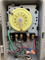
Of course I’ve now run into an issue. In the morning my pump is not kicking on when it should. Instead, I find the breaker tripped. If I manually turn the Intermatic timer on, the pump starts running with no issue. Evidently when the timer turns it on, though, the breaker trips. I tried the potentially cheaper route and replaced the breaker, but I’m still having the same issue. Next up is to replace the timer, however I can’t tell which model I have - I’m assuming T103 or T104. Any help IDing the model would help, or any other input on my issue! TIA
F8D9E80D-8D1E-463A-887B-1DF7D2843431.jpeg
 
Y,

You have a T104 because you have 240 volt timer.

Not sure I fully understand your wiring. Tell me what else is wired into the timer box?

I assume the bottom left conduit is for the pump, what is the bottom right conduit for?

Thanks,

Jim R.
 
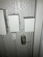
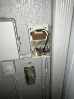
Here is a bigger pic of the timer box… left side goes to the breaker panel, bottom left goes to a flip switch and then down to the pump. Bottom right goes over to an Intermatic labeled box, which I opened up to show in the second pic.B111EA36-E57C-4F4E-B795-BA8B21A10A4F.jpeg

70114EB7-FB35-4828-855E-FC1370803D5B.jpeg
 
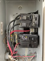
Can you give us a picture of the circuit breaker, is it a GFCI (it should be).

Mechanically there is no difference between the timer tripping the switch in the timer and you manually flipping it, I can't imagine any fault in the timer that could give the symptoms you describe. But is it possible there is an issue with the pump that is causing the breaker to trip after a delay, could be an intermittent ground fault or something worse.

I would suggest removing the on/off tabs entirely from the timer dial, switch the pump on and let it run for a while to see what happens.
 
Neither of those breakers are GFCI.

Both pump and lights should be on a GFCI CB.

What CB is for your pump? That 50A CB looks like it feeds something with the conduit going down.

You have very convoluted electrical wiring. I would bring a licensed electrican in who can bring your wiring up to code and explain to you how everything works.
 
Last edited:
The 50 amp breaker probably goes to a heat pump.

The 15 amp breaker goes to the pump.

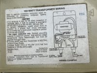
Is the Intermatic a transformer for the lights?

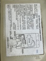
Can you show the label from the transformer door?

The pump breaker should be GFCI.

If the lights are low voltage, they won't require a GFCI.

Since the pump breaker is not GFCI, the trip is probably a short in the timer, switch or wiring.

Most likely the short is not making a solid connection to ground and that is why the trip does not happen consistently.
 
Last edited:
  • Like
Reactions: Jimrahbe
680.23 Underwater Luminaires.

(A) General.

(2) Transformers. Transformers for underwater luminaires shall be an isolated winding type with a grounded metal barrier between the primary and secondary windings, and shall be listed for the purpose.

(3) GFCI Protection. Branch circuits supplying underwater luminaires that operate at more than 15V shall be GFCI protected.

(4) Voltage Limitation. Listed underwater luminaires shall not operate on circuits over 150V.
 
Last edited:

Enjoying this content?

Support TFP with a donation.

Give Support
The 15 amp breaker might be too small for the pump.

If the pump is 12 amps or less, then 15 amps is acceptable.

If the pump is 12 amps or more, I would go to a 20 amp GFCI breaker.

I would replace the breaker and check the timer, switch and wiring for any sort of short or defect.
 
Looks like you have low voltage lights at 12 volts, so no GFCI required.

I would replace the pump breaker and check the timer, switch and wiring for any sort of short or defect.

Check in the pump wiring compartment for any nicks in the wire insulation.

1670780396987.jpeg
 
Separate neutral bar and ground bars are not visible in that sub panel.

It looks like there are neutral lines in the wiring and no clear visibility into how a GFCI gets properly connected.

The wiring is not 240V only and probably requires proper connecting of the GFCI neutral pigtail and neutral from the light transformer.

It looks like 120V for the light transformer is being picked off from a 240V CB.

There is a bunch of complexity in that wiring that requires a knowledgeable electrician.
 
Last edited:
  • Like
Reactions: proavia
I have already replaced the pump breaker so let’s see.
What pump do you have?

The Breaker needs to be GFCI.
Separate neutral bar and ground bars are not visible in that sub panel.
The neutral looks ok.
It looks like 120V for the light transformer is being picked off from a 240V CB.
The light power comes from a panel upstream, so we cannot see what breaker goes to the lights.
 

Enjoying this content?

Support TFP with a donation.

Give Support
Thread Status
Hello , This thread has been inactive for over 60 days. New postings here are unlikely to be seen or responded to by other members. For better visibility, consider Starting A New Thread.