Best SWG retrofit plumbing approach

Fuldo

0
Silver Supporter
Nov 23, 2017
235
Port Orange, FL
I'm getting close to purchasing the CircuPool RJ-30 SWG system as mentioned in another recent post. I've started to consider how to retrofit it and could use some advice.

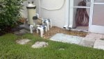
A picture of my present arrangement is shown in the attachment. The output from the filter first goes to a valve that allows some of the water to be diverted to a few spray jets that require very little water when run and they are seldom used. The return line then goes to another valve that used to allow some water to be diverted to a waterfall but that waterfall has been removed and the line capped-off. The water continues to the "main return" (return jets). There is a Hayward CL200 feeder presently in the system that hasn't been used since converting to liquid chlorine about two years ago. Some pipes are buried and I haven't dug to the lower ones yet to fully understand how they are interconnected. However, I'm assuming that the main return line passes through the CL200 feeder and the SWG cell could be simply replace the feeder. I'm thinking that the vertical pipes to and from the feeder could be cut just above ground level and a loop with the SWG cell and flow sensor could be placed there.

Questions:
1) Does this seem like a reasonable approach?
2) Is it worth digging to expose all the underground pipes first to understand the exact plumbing?
3) Is a vertical loop easiest (simply extending the two vertical pipes and add a cross-over pipe) or is there a better way?
4) Does it matter if the cell and/or flow sensor is horizontal or vertical or is this simply personal preference?
5) I noticed the RJ-30 cell has a clear plastic housing. I'm concerned about exposing that to direct Florida sunshine although it would probably only get late afternoon sun where it would be. Does anyone shade the cells to avoid degrading the plastic?
 

Attachments

  • 2013-07-26_10-14-22_186.jpg
    2013-07-26_10-14-22_186.jpg
    98.2 KB · Views: 117
Removing the CL200 and replacing it with the SWG is the right approach.

You don't need to dig up around the pipes but you do need to determine which way the water flows to properly orient the SWG and flow switch.

Review the Circupool RJ manual pages 16-17 Circupool Salt Chlorine Generator Help and note that you need about 20" for the flow switch and cell. See if you would have the space to mount them horizontally between the pipes. Otherwise you need to mount them vertically. Make sure you have the flow switch and cell properly oriented in the water flow.
 
F,

If you mount the switch in a vertical pipe, make sure that "gravity" will open the switch when the pump is off..

Personally, I would try and mount it horizontally, even if I had to widen where the input and output pipes came out of the ground. But, that is just me... :rolleyes:

Thanks,

Jim R.
 
Just make sure you glue the flow switch in the correct direction. It's easy to forget since the arrow on the pvc can be hard to see and an afterthought when trying to glue. how are you on the electrical hook up of this? It's easy but took me a while b/c I had never done it before so I kept looking for sources to make sure i was okay.
 
Thanks everyone for your thoughts and advice. The RJ-30 system has been ordered and is on the way.

The CL200 input side is supposed to be the side where the control knob is. However, I don't trust the guy who replaced my pump and filter and reconfigured my plumbing right after I purchased this house. I'll likely dig down to expose some of the lower pipes so I'll have confidence in the flow direction and maybe allow me to stretch the "run" between vertical pipes without adding additional elbows. Like Jim I think I'd feel more comfortable with horizontal mounting and maybe everything mounted in the same length of pipe. A horizontal run close to the ground would also be less obvious from the street. As a sanity check maybe I'll run the pump for a split second after the pipes are cut just to confirm direction of flow.

I am an engineer and comfortable with electrical work so I'm not intimidated with installing the system myself. I also have a close friend who is a master electrician licensed in many southern states who could give me some guidance and perhaps even assist. Perhaps the biggest question is regarding "bonding". This pool and electrical system has been in-place since the 90s and if there's a "ground" at all it's a local stake near the pump and not the elaborate systems often specified in electrical codes these days. I believe the RJ-30 controller is supposed to be connected to the "bond" as well as to the electrical ground. I'll get it figured out.
 
Hopefully your pump has a bonding wire connected to it, if so just clamp a bonding wire from the SWG to the pump bonding wire. If the pump doesn't have an existing bonding wire then I will not give you any advice on how to bond your system.

Does your pump run off a timer or is it a VS pump with its own timer? It is best to have the SWG and pump on the same timer so the SWG can not turn on without the pump running if the pump is not VS.
 
I have a mechanical Intermatic timer connected to a single speed pump. I plan to connect the SWG to the output side of the timer that also powers the pump. This seems to be the most common approach when using a single speed pump with timer. I'll need to figure-out what sort of bond/ground wires exist but connecting the SWG to a pump bond wire that I think exists makes sense.
 
I installed the RJ-30 system Sunday. On Saturday I dug-out the pipe area to expose the underground pipes and found the area had so many intermingled pipes it was almost impossible to replumb at that level. The length between the uprights where the existing chlorine dispenser was was slightly too short for the RJ-30 cell so I thought I'd jog one leg just above ground level to form a longer run. I lucked-out when the two vertical pipes spread slightly when the chlorine dispenser was cut free. It turns-out the distance was 1/4 inch longer than the absolute minimum needed. The end result was that I was able to place the flow switch in the incoming vertical leg (with gravity opening the switch) and stitched the cell into the horizontal leg. I spent far more time excavating, exploring my options and doing landscaping than on the actual installation. The system seems to work great even when showing a water temperature as low as 58 degrees (the spec was 60 degrees minimum). The water temperature and salt level displayed are spot-on. Salinity is now 3400, I overshot the 3000 I was seeking but the manufacturer suggests 3500 as optimal anyway. I was surprised to find my initial salt content was 1600 considering the water was fully replaced 7 years ago and no salt has ever been added. I set the pump to 4 hours per day and the SWG output at 40% and will monitor performance the next few days. I suspect I'll be able to drop the output some, at least for this coldest part of the season.
 
Thread Status
Hello , This thread has been inactive for over 60 days. New postings here are unlikely to be seen or responded to by other members. For better visibility, consider Starting A New Thread.