- Apr 20, 2021
- 14
- Pool Size
- 10700
- Surface
- Vinyl
- Chlorine
- Salt Water Generator
- SWG Type
- Intex Krystal Clear
Hi all,
As I have no much time, I'm gonna share what I have (is working now in my SWG). Remember that is a Work In Progress code, so any contribution or idea will be very much appreciated.
For this project, original cable between display board and main board will now be from display board to ESP32 board. You'll need a new cable to connect ESP32 board to the main board. This way the ESP32 will be in the middle of every comunication. For the new cable I used a NEMA17 motor cable (the one that 3D printers use) as I had several ones at home, and one connector fits what I need, so only have to change the other connector from this cable.
Here is the repo:

 github.com
For the circuit you'll need:
- ESP32
- Relay module
- Power supply, I used 5V, but you can use 3.3V instead (wiring is different!)
- 2x Female and 1x Male XH2.54 4pin connectors (they are the most similar I've found that fits original cable)
- Level shifter as the logic from ESP32 is 3.3V and the SWG logic is 5V.
- Fuse for the power supply (optional)
- NEMA17 cable (I used this because I had several ones at home, but you can use whatever you have or you can buy)
For the wiring, take into account the ESP32 pins:
- GPIO 19 -> SWG main board clock
- GPIO 18 -> SWG main board data
- GPIO 17 -> Display board clock
- GPIO 16 -> Display board data
- GPIO 0 -> Relay module control
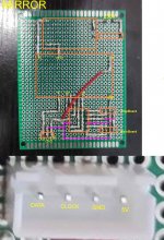
As I haven't done any schematics yet, guessing which wire is everyone on the original cable between the main board and the display board is on you. Check the schematic of the display controller (TM1650) which is in Documentation folder within the repository. The pins you need to check on the TM1650 are the following:
- PIN2 clock
- PIN3 Data
- PIN4 GND
- PIN 10 VDD (+5V)
Once you've indentified these pins, you can easily identify wich pin in the cable corresponds to every pin in the TM1650, and you'll be able to properly connect it to the level shifter, and from here to the proper pins on the ESP32.
Main power wire must be disconnected from the main board within the machine to be able to fully control power from the ESP32 (and avoid turning on itself depending on it's programming). Instead, this cable now goes to the relay module and to the input of the power supply in ESP32 board. The output of the relay goes were the original power wire was connected before on the main board. Now the ESP32 can turn ON and OFF the machine. By default when the system is powered, the ESP32 goes to standby mode, which means the machine has power and can be controlled using the default factory buttons. If the ESP32 powers OFF the machine, it won't be available to be operated using the buttons, and will only able to go back to standy state using the Rest API, or unplugging and plugging back the system. This way I've kept factory behaviour.
Before using the API, first you'll need to configure the WIFI on the ESP32. For that this project includes the wifi manager which allows you to scan and set a wifi configuration easily from your phone, as ESP32 will create its own wifi for that. If you use the console and the USB connection you'll see the assigned IP. I strongly recomend you associate the IP to the MAC address in your router configuration to make sure every time DHCP on your router assings IP to the system, the IP remains the same (I haven't implemented anything yet to specify a custom static IP from the phone).
For the API to control the system there are some endpoints that you could check in the code.
Basic API calls are the following:
- Control the machine
POST http://ip_addr:8080/api/v1/intex/swg
{
"data": {
"power": "{on|off|standby}"
}
}
- Get current status and info
GET http://ip_addr:8080/api/v1/intex/swg
- OTA Update
http://ip_addr:8080
Hope I can find the time to create a propper documentation with schematics, pictures, credits and agreements to other projects that I used. If you have any problem with this or you need help, feel free to ask, I'll try to help you.
Enjoy!
As I have no much time, I'm gonna share what I have (is working now in my SWG). Remember that is a Work In Progress code, so any contribution or idea will be very much appreciated.
For this project, original cable between display board and main board will now be from display board to ESP32 board. You'll need a new cable to connect ESP32 board to the main board. This way the ESP32 will be in the middle of every comunication. For the new cable I used a NEMA17 motor cable (the one that 3D printers use) as I had several ones at home, and one connector fits what I need, so only have to change the other connector from this cable.
Here is the repo:
GitHub - tonyflores1006/intex-swg-iot: ESP 32 code to create a man-in-the-middle between main board and control board of Intex SWG, converting this Salt Water Generator in an IoT device.
ESP 32 code to create a man-in-the-middle between main board and control board of Intex SWG, converting this Salt Water Generator in an IoT device. - tonyflores1006/intex-swg-iot
github.com
For the circuit you'll need:
- ESP32
- Relay module
- Power supply, I used 5V, but you can use 3.3V instead (wiring is different!)
- 2x Female and 1x Male XH2.54 4pin connectors (they are the most similar I've found that fits original cable)
- Level shifter as the logic from ESP32 is 3.3V and the SWG logic is 5V.
- Fuse for the power supply (optional)
- NEMA17 cable (I used this because I had several ones at home, but you can use whatever you have or you can buy)
For the wiring, take into account the ESP32 pins:
- GPIO 19 -> SWG main board clock
- GPIO 18 -> SWG main board data
- GPIO 17 -> Display board clock
- GPIO 16 -> Display board data
- GPIO 0 -> Relay module control
As I haven't done any schematics yet, guessing which wire is everyone on the original cable between the main board and the display board is on you. Check the schematic of the display controller (TM1650) which is in Documentation folder within the repository. The pins you need to check on the TM1650 are the following:
- PIN2 clock
- PIN3 Data
- PIN4 GND
- PIN 10 VDD (+5V)
Once you've indentified these pins, you can easily identify wich pin in the cable corresponds to every pin in the TM1650, and you'll be able to properly connect it to the level shifter, and from here to the proper pins on the ESP32.
Main power wire must be disconnected from the main board within the machine to be able to fully control power from the ESP32 (and avoid turning on itself depending on it's programming). Instead, this cable now goes to the relay module and to the input of the power supply in ESP32 board. The output of the relay goes were the original power wire was connected before on the main board. Now the ESP32 can turn ON and OFF the machine. By default when the system is powered, the ESP32 goes to standby mode, which means the machine has power and can be controlled using the default factory buttons. If the ESP32 powers OFF the machine, it won't be available to be operated using the buttons, and will only able to go back to standy state using the Rest API, or unplugging and plugging back the system. This way I've kept factory behaviour.
Before using the API, first you'll need to configure the WIFI on the ESP32. For that this project includes the wifi manager which allows you to scan and set a wifi configuration easily from your phone, as ESP32 will create its own wifi for that. If you use the console and the USB connection you'll see the assigned IP. I strongly recomend you associate the IP to the MAC address in your router configuration to make sure every time DHCP on your router assings IP to the system, the IP remains the same (I haven't implemented anything yet to specify a custom static IP from the phone).
For the API to control the system there are some endpoints that you could check in the code.
Basic API calls are the following:
- Control the machine
POST http://ip_addr:8080/api/v1/intex/swg
{
"data": {
"power": "{on|off|standby}"
}
}
- Get current status and info
GET http://ip_addr:8080/api/v1/intex/swg
- OTA Update
http://ip_addr:8080
Hope I can find the time to create a propper documentation with schematics, pictures, credits and agreements to other projects that I used. If you have any problem with this or you need help, feel free to ask, I'll try to help you.
Enjoy!