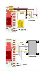
I've bene spending time learning the technical side of the pool equipment. I had a question about the transformer and the two rectifiers. Based on the pictures below, the transformer has two output wires (K - Both Yellow) (to get 24 VAC), but 4 input wires of 120 VAC (H - Gray, Violet, White and Blue). Why does the transformer need 4 inputs of 120 VAC?
Also based on the pictures below. Two Orange Wires (J) with 24 VAC are going to the rectifiers, one to each rectifier. Red and black are coming back from the rectifiers with 18-33 VDC and red and black are connected to each other. Can anyone explain how this circuit works. I understand that rectifiers use diodes to convert AC to DC, but then why use two rectifiers and why are red and black connected to each other and also why do the two orange go to separate rectifiers (assuming one orange wire is hot and one orange wire is neutral with 24 VAC)?
Also based on the pictures below. Two Orange Wires (J) with 24 VAC are going to the rectifiers, one to each rectifier. Red and black are coming back from the rectifiers with 18-33 VDC and red and black are connected to each other. Can anyone explain how this circuit works. I understand that rectifiers use diodes to convert AC to DC, but then why use two rectifiers and why are red and black connected to each other and also why do the two orange go to separate rectifiers (assuming one orange wire is hot and one orange wire is neutral with 24 VAC)?