Anyone tried uploading / downloading firmware from Hayward GLX-PCB-MAIN boards?

I have the SP3202VSP. I had the communication wires connected but disconnected for now so I can use in standalone with its control panel. When it was connected I tried to set the DP to all off and it worked along with the main pump. I tried disconnecting the Aux3 pump and changing the main filter pump from off,off,off,off,off to off,on,on,off,off to see if the option showed up and it still didn't. I found this document that makes me think that option wasn't available until 4.30 of the firmware. http://splashottawa.com/wp-content/uploads/2016/05/Pro-Logic-Diagnostics.pdf
 
Alas, it seems that most of the features I would like to get, via an update, are only available to the newer "Pro" version of the board. The code will not be compatible with a smaller (older) microchip of my board.

That being said, I wouldn't mind trying to develop a custom / homebrew version of the code to improve the user interface and add support a better user interface (I'm constantly disappointed with endless menus and hidden options), for full fledged variable speed pump (better speed display / control), T-CELL 3 / 9 (better re calibration), their new Sense and Dispense tool, as well as support for Aqua Connector (or some sort of other custom wifi remote, perhaps based on raspberry pi).

Keep in mind that I only have a somewhat inaccurate T-CELL 15 (which is reporting salt level at least 200 - 500 ppm lower than store tests even while clean) and an old EcoStar Variable Speed pump (seems they've done some software updates there too), but I would rather spend money on a new sensor (such as their Sense and Dispense package for PH testing / control), rather than a new board.

Oh, and I also have a 3rd party spa heater and a hayward wireless remote for a 16 aux unit (GLX-WW-RF-PS-16), from which I am limited to 4 (so many unused buttons...). I would love to have an option to assign pump speeds / run super chlorinate / or have individual control over all 8 of aux relays, all from buttons I've already paid for.

What would your wish list be for a homebrew code? What features would you like see added?

Cheers,
eePool

P.S. I'm planning on doing this via open source, anyone in a similar position who would willing to help?

Hi, thanks for this. Any idea if this would work with a GLX-PCB-HPC-4? E command board. Same basic system, scaled back a touch.

I’m on to Omnilogic, but my colorlogic Lights are stuck in Networked mode and are useless until I can hook up a prologic rev 4.0 or higher and reset them.

i have everything I need: display, Network module, pcb - but the pcb is rev 3. Hayward has no interest in helping me, and updating the board I got my hands on would alleviate my 6 month struggle to have lights back in my pool.

many thanks for your work.
Dave
 
Hi everyone, I'm new around here, but so far I can't find an update to my Hayward automation system (Aqua Logic AQL, software Revision 3.00). What software version do you have?

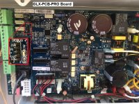
Inside, I have one of these "main" boards.

View attachment 69436
Here I noticed that J12 header (located at the top left corner, between wireless antenna connector J9 and Local Display connector J7) is a standard pic programming port (matching pickit well)
View attachment 69437
(Pin 1 is located to the left, closer to J9 connector, pin 6 is unused and thus J12 has only 5 pins)

For this, you will need a microchip PicKit 3 programmer, available via official channel for $48 here (link), or Amazon has some knock-offs for less here (link), though why so many of them are more than $48 are beyond me.

The microchip in question is PIC18F2620 and you can interact with it by:
  1. Install a free mplab-x from here (link)
  2. Lunch mplab ipe (integrated programming environment), which was installed along with mplab-x
  3. Go to Settings > Advanced mode (password is "microchip")
  4. Under Family, choose "Advanced 8-bit (pic18)"
  5. Under Device, choose "PIC18F2620"
  6. Make sure that target board is not powered (main circuit breaker is OFF or the board is removed from the assembly), working with a live board is risky
  7. Back in IPE, Under Power tab, Choose 5.0 as VDD voltage and "Power Target Circuit from Tool" option (If you don't see power tab, check step #3)
  8. Go back to Operate tab and click Connect
    • The first time you are connecting, IPE may update your programming tool, it is normal
  9. First thing you NEED to do upon successful connection is click "Read" which is located in the middle of all the options
  10. After a successful read command, identified by a blue, time-stamped "Read Complete" status line on the output:
  11. Choose File > Export > Hex and SAVE the file somewhere safe (you may want to even email yourself this file). It will allow you to restore everything if all else has failed.


What I hope to accomplish is to get this community involved and allow us to finally update our automation controllers without the need to purchase the whole new Main Board, as seem to be the going suggestion to date (link).

By sharing the firmware, we can use the similar method described above to load more up-to-date firmware (via File > Import > Hex) and Program command instead of Read.

As I've mentioned, I only have access to version 3.0 of the firmware, which I will be happy to share as soon as I had a chance to cooperate with other members on data within EEPROM. I don't want someone loading out of date firmware and potentially breaking their controllers.

Anyone out there with a pickit handy and a more up to date firmware on their device?

Cheers,

eePool

Do you need version 2.5? I can upload that if you have any use for it.
 
Hi Everyone,
Anyone here with firmware 2.65 or newer for AquaLogic board?
I need to update to be able to install Tristar VS Pump.

Thanks

Your Aqualogic board cannot be updated the way newer Prologic and OmniLogic boards can.

 
I tried to flash an old aqualogic board firmware 2.15 to 2.91 with pickit 3, but it “Failed to program device.” laptop only provided 4.625V, so I Had to use my desktop at 4.85V to get connected to the pickit (not enough voltage to connect at 5V)

2021-03-23 23:54:49 -0700 - Programming...

Device Erased...

Programming...

The following memory area(s) will be programmed:
program memory: start address = 0x0, end address = 0xfc7f
configuration memory
EEData memory
program memory
Address: 0 Expected Value: fb Received Value: fa
Failed to program device
2021-03-23 23:54:52 -0700 - Programming failed
Pass Count: 2

The error in screenshot was what appeared when I first connect to the pickit3. my suspicion is that board is too old (incompatible with 2.91) or voltage too low (<5v)...

when I did a read and export, save then program the same file back it completed no problem.

Anyone (@eePool )can tell or guess what the issue could be and what to try next? Looking to try a lower firmware that support VSP if I can get my hands on one.
 

Attachments

  • C1DCE2F7-393D-496D-9BD5-4B7BD1605D9F.jpeg
    C1DCE2F7-393D-496D-9BD5-4B7BD1605D9F.jpeg
    238.3 KB · Views: 26
  • E74443CE-068B-40EC-BCFD-F5D8F76A714E.jpeg
    E74443CE-068B-40EC-BCFD-F5D8F76A714E.jpeg
    327.7 KB · Views: 26
  • 3014FBD2-8921-4108-B07B-4DD53726F885.jpeg
    3014FBD2-8921-4108-B07B-4DD53726F885.jpeg
    269.9 KB · Views: 26
Last edited:
@eePool @TexasBrian - after some digging, It looks like my chip is PIC18F252 and not PIC18F2620 as in the first post. I confirmed it by shining a bright flashlight on the back of the chip to read the tiny numbers. what a bummer! firmware 2.91 I got likely won't work, it's throwing a warning below. not sure if there's a firmware that can support VSP for this chip out there.

*****************************************************

Connecting to MPLAB PICkit 3...

Currently loaded firmware on PICkit 3
Firmware Suite Version.....01.49.09
Firmware type..............PIC18F

Programmer to target power is enabled - VDD = 4.875000 volts.
Target device PIC18F252 found.
Device ID Revision = 7
2021-03-24 01:27:00 -0700 - Reading...

Reading...

The following memory area(s) will be read:
program memory: start address = 0x0, end address = 0x7fff
configuration memory
EEData memory
User Id Memory
Read complete
2021-03-24 01:27:07 -0700 - Read complete

Exporting hex file...
2021-03-24 01:27:45 -0700 - Hex File successfully created at C:/drivers/Aqualogic Firmware/PIC18F252-v2-15.hex
2021-03-24 01:27:54 -0700 - Loading hex file. Please wait...
Loading code from C:\drivers\Aqualogic Firmware\GLX-PCB-MAIN_firmware_v2_91.hex...
Warning: C:\drivers\Aqualogic Firmware\GLX-PCB-MAIN_firmware_v2_91.hex contains code that is located at addresses that do not exist on the PIC18F252.
Code incompletely loaded.
2021-03-24 01:27:55 -0700 - Hex file loaded successfully.
 
So think I have officially bricked my Aqualogic PS-8 by unknowingly flashed my chip with a PIC18F2620 device (64kb program memory size) selected in MPLab IPE before finding out mine's a PIC18F252 chip (32kb program memory size). Display now shows "Communication Err 2" meaning no communications from the board. Hex file read from the chip showed half the size of v2.91 copy I used to flash it with. (~90kb vs. ~183kb). Totally my fault as I was careless, the backup copy didn't work because it was read as a PIC18F2620 (read showed successful but actually were all zeros.) I'm throwing this out here in case someone else wants to try flashing their board, be double sure the chip matches up first.

I'm now looking for any other Aqualogic GLX-PCB-MAIN firmware versions to try to re-flash it. The original firmware version was 2.15. if you have one, I'd appreciate a PM. Thanks.
 
Just to clarify, I am looking for ANY firmware version, not just 2.15. I'd be happy if I could get my board working again.
As a last resort, I might try to replace the chip with a new PIC18F2620 ($15) and flash it with V. 2.91, if there's a chance it could work.
 

Enjoying this content?

Support TFP with a donation.

Give Support
Update - I was able to grab an aqualogic version N board from ebay for cheap with firmware 2.93. many things look different, I can see why I should not have flashed a newer firmware to the older board. But I'm a bit disappointed as it can only recognize 2 speeds (high/low) from the Ecostar VS. should have just used the relays for different speeds, and save the trouble.

anyone running into this thread and try to flash your firmware - don't do it, unless it's the same board version.
 
  • Like
Reactions: doublespaces
Thanks eePOOL, the info was really useful. I have been trying to get info from Hayward on firmware revisions as I ad a GLX-PCB-PRO running v4.10 firmware. I wanted to use the AQUA-CONNECT and v4.2 was the minimum firmware that works with the AQUA-CONNECT. I purchased a new PCB and I started to look around for firmware updates to see if I could at least use my old board as a spare. I came across your blog. You get an A+ for detail. It was so good it motivated me to DIY. The first issue I encountered was the microchip is different on the GLX-PCB-PRO and identification marking on the chip is so feint as to be almost invisible. With the aid of a powerful magnifying glass and a powerful light I ascertained that the chip on the GLX-PCB-PRO is a PIC18F4685. If there is anyone interested in updating the GLX-PCB-PRO then following eePool’s instructions will work if you select the PIC18F4685 chip type. The chip also uses vdd of 5.0v. This is present on pin1 which is the lowest pin. Instead of consigning my v4.10 firmware board to scrap I was able to update it to v4.46 by cloning from my new board.

Has anyone had any luck decoding the hex code with a view to personalizing the control functions?
could you send me the 4.46 firmware? i have a pro board with old software on it
 
I went ahead and purchased a knock off version of the pickit3 from Amazon. I had the local hayward tech come out this past week and he upgraded my firmware from 4.20 to 4.46 on my main board to get better funcions/options out of my Tristar 950 VSP.

I had picked up a spare prologic controller locally to have and extra dispaly/board/parts in case anything goes out on my system. The board had main software of 4.30. I went ahead and copied the 4.46 firmware from my main board and flashed the firmware to the spare board. Happy I can just swap boards now if ever needed. Thanks for the instructions posted above.
I know it’s an old thread but do you or anyone have 4.46 firmware they can share? I am looking to upgrade from 4.20 and the board supports it. Just don’t have the firmware.
 
I know it’s an old thread but do you or anyone have 4.46 firmware they can share? I am looking to upgrade from 4.20 and the board supports it. Just don’t have the firmware.
If you have the pickit 3 programmer I can send the hex dump of 4.47 as soon as my pickit 3 arrives next week.
 
Here is the latest glx-pcb-pro 4.47 firmware
 

Attachments

  • PIC18F4685.zip
    76.8 KB · Views: 6
  • FA1AD6E7-760F-4003-8207-88D991E9C33D.jpeg
    FA1AD6E7-760F-4003-8207-88D991E9C33D.jpeg
    326 KB · Views: 28
  • 4C741548-09C0-4BD9-AA9A-55A78D97246B.jpeg
    4C741548-09C0-4BD9-AA9A-55A78D97246B.jpeg
    743.7 KB · Views: 31
  • Like
Reactions: doublespaces
I know it’s an old thread but do you or anyone have 4.46 firmware they can share? I am looking to upgrade from 4.20 and the board supports it. Just don’t have the firmware.
Here is the ver 4.47 firmware. NOTES: This is for the glx-pcb-pro PRO board, NOT the MAIN board. On the PRO board header to plug into is designated J10. 5 pin, black in color, oriented VERTICALLY, and is located on upper left side. (If you have a horizontally oriented J12 header, you have a MAIN board and this firmware is NOT for that board)

To plug in to board, remove male adapter end on the 6 pin connector included with your pickit3. (you will not use pin 6) Lowest pin on that connector (on5 pin of board) is the #1 pin. So if you were to plug the 6 pin connector into your pickit3 with white wire where the arrow is (that's pin 1on the pickit3) then you'd plug the other end of the cable into yourboard with white wire on lowest pin. (black wire will not plug into anything) Oh, and use 4.75V setting on MPLAB X IPE program under power option to power board with tool. 5V setting would not work for me.
 

Attachments

  • PIC18F4685.zip
    76.8 KB · Views: 5
Did a bit more research, and it seems there is an updated "GLX-PCB-PRO" version of the board:
GYGG0nM.jpg


This board also seems to feature the programming port J10 (shown within the Red circle above). I can't tell what is pin 1 from the any pictures I could find, but if you have this board, you can find it using a volt-meter while the board is powered up.
Pin 1 will have 3.3 to 5V (not sure which, not knowing the processor) relative to pin 3 (middle pin).

According to the official PDF (here), the latest version (as of 4 years ago) is 4.45.

Lowest pin is pin 1.

Here is the updated 4.47 firmware.

NOTES: This is for the glx-pcb-pro PRO board, NOT the MAIN board. On the PRO board header to plug into is designated J10. 5 pin, black in color, oriented VERTICALLY, and is located on upper left side. (If you have a horizontally oriented J12 header, you have a MAIN board and this firmware is NOT for that board)

To plug in to board, remove male adapter end on the 6 pin connector included with your pickit3. (you will not use pin 6) Lowest pin on that connector (on5 pin of board) is the #1 pin. So if you were to plug the 6 pin connector into your pickit3 with white wire where the arrow is (that's pin 1on the pickit3) then you'd plug the other end of the cable into yourboard with white wire on lowest pin. (black wire will not plug into anything) Oh, and use 4.75V setting on MPLAB X IPE program under power option to power board with tool. 5V setting would not work for me.
 

Attachments

  • PIC18F4685.zip
    76.8 KB · Views: 5
Did a bit more research, and it seems there is an updated "GLX-PCB-PRO" version of the board:
GYGG0nM.jpg


This board also seems to feature the programming port J10 (shown within the Red circle above). I can't tell what is pin 1 from the any pictures I could find, but if you have this board, you can find it using a volt-meter while the board is powered up.
Pin 1 will have 3.3 to 5V (not sure which, not knowing the processor) relative to pin 3 (middle pin).

According to the official PDF (here), the latest version (as of 4 years ago) is 4.45.
 

Attachments

  • 9CCB4BBC-4A3D-4D1E-883C-ECEA96FF7BDB.jpeg
    9CCB4BBC-4A3D-4D1E-883C-ECEA96FF7BDB.jpeg
    326 KB · Views: 14
  • 205D0D8D-CF69-48EA-972C-088E823C1B87.jpeg
    205D0D8D-CF69-48EA-972C-088E823C1B87.jpeg
    743.7 KB · Views: 13

Enjoying this content?

Support TFP with a donation.

Give Support
Thread Status
Hello , This thread has been inactive for over 60 days. New postings here are unlikely to be seen or responded to by other members. For better visibility, consider Starting A New Thread.