Alternative Pool Automation and Sensor/Chemical Control and Integration

MyAZPool

Gold Supporter
Jul 3, 2018
2,296
Arizona
Pool Size
20500
Surface
Plaster
Chlorine
Salt Water Generator
SWG Type
Pentair Intellichlor IC-60
Industrial Automation 8-Layer Stackable Card for Raspberry Pi Pool Automation and Sensor/Chemical Control and Integration
(nodejs-poolController / nodejs-poolController-dashPanel / relayEquipmentManager)

2020-12-05_08-13-53.jpg

- Table of Contents -

- Preface

1. Background, Purpose and Scope

2. Credits

3. Alternative Automation Enclosure and Related Hardware

a) Enclosure
b) AC Power Requirements and Related Support Equipment
c) DC Power Requirements and Related Support Equipment
d) Network Connectivity
e) RS-485 Connectivity

4. Sensors, Probes, EZO-Circuits and Hosts
a) Overview
b) Probes and Sensors
c) Sensor/Probe Mounting Considerations
d) Initial Sensor Setup and Configuration

5. Additional Miscellaneous Information
a) Calibrations
b) Atlas Scientific IoT Monitoring Software
c) Other Atlas Scientific Kits

6. Useful References and Links

7. Glossary

8. Additional Photographs with Related Comments


Preface –

This document concerns itself with advanced and alternative pool automation, sensor and chemical control and integration.2021-01-01_18-47-35.jpg

Nothing discussed in the initial posts of this thread are actually “necessary” for the provision or the operation of basic pool automation or control. All of the methods or procedures discussed below should be considered “above and beyond” what is necessary for the majority of pool owners considering pool automation and control

With regards to this newly completed project of mine, there are basically two major components that comprise the overall system - Hardware and Software. This document concerns itself with the hardware component of the system.

The software component is in the final stages of initial development and is currently in beta testing.

Once that beta testing is complete and the software is released by the developer. Then a follow-on companion document titled “Relay Equipment Manager (REM) and Integration with nodejs-poolController and dashPanel - Information and User’s Guide”, will be published.

A draft outline of the Information and User’s Guide is provided here for reference purposes.


1. Background, Purpose and Scope
Several months ago, particular discussions among several TFP members began to develop online and off-line. These discussions centered around the various design and implementation considerations of a more robust level of pool automation incorporating sensor/chemical control and applicable integration with existing automation systems.
2021-01-02_11-39-40.jpgThese discussions became more involved and detailed over time. Not only due to the fact that the nodejs-poolController and associated nodejs-poolController-dashPanel software had developed into much more comprehensive and dynamic platforms. But in addition, both were becoming more “mainstream” as well.
(Please refer to the glossary for definitions of nodejs-poolController, nodejs-poolController-dashPanel and REM)

Several members here (including myself) were having enhanced success with these two programs that by all accounts, were exceeding expectations.

Also, others were having increasing success from their own “DIY” or “homebrew” pool automation and sensor/chemical control systems as well.

The last element that served to enhance the progression of these discussions was due to the fact that several individuals were involved in an ongoing project to “jailbreak” or “crack-the-code”, with regards to the Pentair IntelliValve actuator and its RS-485 command structure. This brought several individuals into an off-line group with a synonymous goal. Consequently, various other alternative pool automation topics and discussions developed over time.

As these discussions concerning various advanced pool automation topics further developed, I began to seriously consider “upgrading” my current automation system. I started to imagine just what the possible end results might be. Especially since I had just recently upgraded my automation and pool control from merely using the Pentair IntelliCenter Web Client and iOS Mobile app, to using the more “user-friendly” nodejs-poolController-dashPanel. After many months of using this new controller, I really considered it to be a major “step up” when compared to that of the Pentair platforms and the many pitfalls that reliance on those pathetic platforms brought.

I began to realize however that if I opted to further upgrade my pool automation and control, it would indeed be a major undertaking. One thing quickly became clear to me. If this upgrade were to be performed in what I considered to be a correct manner, then not only would I be required to add many new and key components to my current automation “mix.” But, that I would also need to fully integrate the “new” with the existing.

That would require a major retrofit. It would require many modifications to my equipment pad as well as existing plumbing. It would also require modifications to both low voltage and line voltage circuitry throughout my equipment pad. And not only that, but my IntelliCenter OCP Load Center would also require some retrofitting/modifications as well.

Please refer to the following link for detailed information regarding the various modifications that I made to my equipment pad and the retrofitting of my IntelliCenter OCP Load Center.

Note 1: Much of the methodology explored throughout this discussion is based solely upon my own self-imposed requirements and personal experiences. Many times, there are different methods which one can utilize in order to arrive at the same solution. So if other options are not specifically mentioned here, it does not necessarily imply that they cannot be realized.

If you think that you might have an improved option or solution, explore it and then please share it here on TFP for the benefit of all.

Note 2: Throughout this discussion, I have provided photographs and/or illustrations where applicable. In addition, at the end of this document I will provide a number of photographs with related comments that illustrate some of the various activities that were performed during the course of this project.

However, due to some total image limitations and to provide for possible edits in the future, I broke this document up into several posts.

Note 3: In the near future. I plan to provide a “parts list” of items that were utilized during the course of this project and that were not specifically addressed or mentioned in this initial discussion.

Note 4: The information contained within this document is meant to be dynamic rather than static. In other words - a “living” document that is intended to reflect various future changes or improvements in methods, future equipment or devices, software/firmware releases, and to address any information that may become outdated with future edits and updates.

Note 5: A good deal of this discussion concerns itself with the installation, configuration and the use of chemical sensor/probes, pool chemical dosing components and their related monitoring, reporting and event driven software.

However, nothing in this document should be construed as to suggest that regular and timely “manual” pool water testing should ever be completely abandoned. On the contrary. Electronic components and software sometimes fail and just like with any other chemical controller - Complete and total reliance on automation and automated chemical control is NOT advised.

Chemical automation and sensor results should ALWAYS be reinforced or validated using industry-standard “manual” pool water/chemical testing. Especially when any doubt exists regarding the validity of any critical sensor readings (pH and/or ORP.) The same holds true for filter pressure transducer readings. “If in doubt, check it out.”

In addition, the discussions contained within are specifically applicable for outdoor / uncovered swimming pools. Indoor or covered pools require special or different considerations with regards to chemicals and swimming pool chemical management.

Note 6: And lastly – In my opinion, this project was a success and a huge “step forward” for me personally, as it relates to my pool automation and sensor/chemical control.

However, in the interest of “full disclosure,” I should note that things didn’t always go according to plan and yes there were setbacks. No project of this magnitude is ever without mistakes and miscalculations. That is the primary reason for the sharing of this information. In the event that others may consider a similar project, hopefully there are some beneficial “take-aways” here that can be realized by others.

As I will note in the following section, I had a lot of help. But, at the same time I was putting together many different components that some individuals had experience with and other’s may have had experiences with different components, uses or arrangements. In other words, there were times that I felt like I was “trailblazing” some new paths here. There were no real guidelines or instructions to follow. That’s really not an experience that can give you that “warm and fuzzy” feeling.

Sometimes there were “steps” backwards. And I won’t lie. At times, there was some stress involved. But no matter a minor “speed bump” here or there, there was always momentum forward and the train did continue to “roll down the tracks” to it’s final destination.

In the end, this project exceeded my expectations. And for the most part I really enjoyed myself throughout. Friendships were strengthened and I experienced a camaraderie with fellow TFP members who harbor the same specific type of pool automation interests as I do.


2. Credits
Although this thread has been initiated by me and I had the opportunity to assist where possible in some of the component and software testing (beta-tester). I am merely sharing my own particular experiences, methods and results. There is quite a bit of material contained within this discussion as well as the follow-on REM Information and User’s Guide, which is the direct result of advanced software programming work and/or the knowledge and expertise of others.

I’m creating this thread mostly for the benefit of others who may have similar ambitions in the future. However, I want to ensure that I don’t give a false impression that I am somehow responsible for the conception of this level of pool automation, sensor and chemical control. I’m not that smart by any means. ;) In the end, I am merely the beneficiary of other’s intense work, time and knowledge.

I would personally like to give credit and “shout-outs” to the following individuals for their amazing assistance to not only me with regards to this project. But to the many others that they have assisted as well, when it comes to alternative or advanced pool automation and related topics.

@cmc0619 and @Katodude These two TFP members were the “originals” who convinced me that there was pool automation “life” beyond the Pentair IntelliCenter. They have been exploring “alternative pool automation” for a while now and it is due to them mostly that I began this journey. They were the ones that initially pointed me in the direction of the nodejs-poolController and nodejs-poolController-dashPanel.

They were always there when I strayed and they have done well keeping me “between the lines.” Thanks much for all of the time and assistance guys! I have learned a tremendous amount from you two and I’m still learning.

Besides, they promised me cookies if I would explore the “dark-side” of pool automation and control. How could I resist that temptation?

@rstrouse and @tagyoureit These two software programmers are the developers of nodejs-poolController and its associated webClient, the nodejs-poolController-dashPanel and REM.

And they operate their own Pentair automation systems as well. Note: In my opinion, it’s a “win-win” for users when the developer of a product is also a regular user of that same product.

These are the “super-smart” guys that get all of the credit when it comes to the amazing development of these software products that several of us now or will in the future, reap the benefits of using.

I really can’t thank them enough for the sharing of some of their knowledge and their tremendously helpful advice and assistance to me throughout this project. Also for their development and continued upgrades of the above mentioned software platforms.

And certainly, for their patience and for “putting up” with a “noob,” who until 8 months ago or so, didn’t even know what a Raspberry Pi was. Heck, at first - I thought it was some sort of a desert that you baked in the oven. :p

Lastly, much of the work by @mcqwerty, @guinness, @segalion and his RaspiPool, segalion/raspipool (great work there), @jonpcar, @dradam and others too numerous to name here, have been inspirational to me regarding this type of advanced and alternative pool automation and sensor/chemical control.

Many, many thanks to all of the above for opening up this new world of “alternative” pool automation to me! It’s been quite the ride over the 2nd half of 2020. :thumleft:

2021-01-08_18-45-34.jpg

Note: Some images contained within this document are the courtesy of – Atlas Scientific Environmental Robotics


3. Advanced Automation Enclosure and Related Hardware
2020-12-29_14-35-06.jpg 2021-01-03_11-19-23.jpg

In this section I will explore my new automation enclosure as well as the hardware housed within.

Note: Here, you will find my own particular experiences. This will include the equipment that I ultimately selected to incorporate in this automation system and why. However, this was just “my way” and nothing here is intended to suggest that there are not different methodologies or different equipment that cannot be used in order achieve the same result.

a) Automation Enclosure

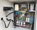
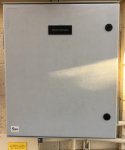
One thing quickly became apparent to me in short order if I was even going to get this project “off-the-ground.” I would be required to install a weatherproof enclosure at the pool equipment pad in order to house the required electronics.

I had initially inquired of others, if I could possibly “run” some of the sensor control cables to the house and then install the necessary Raspberry Pi micro-computer and related components there, instead of at the equipment pad. That idea was quickly discounted, as the distance for some of those types of signals from the sensors and probes would be excessive. Along with that fact, I had determined that I would not be able to house all of the required components within the existing IntelliCenter Load Center.
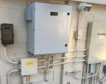
2020-11-29_20-12-03.jpgSo it was settled. The micro-computer and other key and related electronic components would require housing within a weatherproof enclosure. And the location of this enclosure would be required at the pool equipment pad.

After discussions and research that involved what components would be required. As well as considering provisions for enclosure cooling (I reside in central Arizona where summer outside temperatures are typically in the high teens). I then set to work to find the right enclosure for those requirements.

During the course of discussions with others, it had become apparent to me that I would require “DIN rail mounting” for the many components that would be housed within this enclosure.

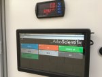
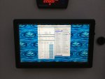
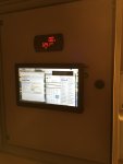
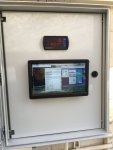
Based on some additional research, I determined that I should consider installing a small touchscreen monitor at the equipment pad as well. My reasoning was that this requirement would greatly facilitate some initial sensor configurations while I was physically at the pad. And in addition, I thought it might be helpful when sensor calibrations would be necessary.

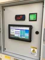
Although not actually a “requirement” per se, I have indeed found the touchscreen monitor to be very useful at the equipment pad. I can control all of the sensors and devices from this touchscreen monitor to include REM and the IntelliCenter via the nodejs-poolController-dashPanel. I can of course, do the same thing from my Mac, iPad, iPhone, etc. however.
IMG_6471.JPG
Consequently, I decided upon Altelix as the manufacturer of a selected enclosure. This decision was based on recommendations, features and reputation.

Using my basic plans and requirements as my guide. And based on consultations with the Altelix sales team. I settled on a 24x20x9 Industrial DIN Rail Enclosure, Fiberglass, NEMA 3X, IP65 enclosure.

Unfortunately, this model did not come bundled entirely with the configurations that I required. Consequently, it would require some “a-la-carte” additions to it as well. The additions included items as listed below:

- An inner door where I planned to mount an Elecrow 10.1” 1920x1080p HDMI IPS Touchscreen Monitor as well as my existing Precision Digital ProVu Pulse Input Flow Rate/Totalizer Meter for the automatic pool fill/leveler.


EDIT: 7/6/21... Since the initial publication of this document, I have also added a FlowVis Digital to the mix. Hence, I mounted the FlowVis Digital Panel Display to the inner door and connected the 4-20mA outputs to the Sequent Microsystems Industrial I2C Automation Raspberry Pi Stackable Card.
C837FAC6-F4F0-4E5E-8909-B9D3327ACF7E_1_105_c.jpeg EE983755-8F11-448B-9301-E991B303ED59_1_105_c.jpeg

- Mounting Kit.

- A cooling fan setup to include two (2) each, 120/240 VAC 4” enclosure type fans. Associated Fan Filters, Guard Screensand two ABS Vent/Fan Shroud Kits were also required. A thermostat to control the fans was NOT included in this order however. I discovered that Altelix does not sell enclosure fan thermostats separately but only when bundled with certain “kits.” Consequently, I would be required to look elsewhere for the thermostat.

- Additional DIN Rail Mounting Kit which includes two DIN rails and hardware. Two rails and hardware are included with the enclosure but I had calculated that I would require an additional two.

Lastly, I had to assemble most of the above. That was not really a problem. In addition, I would have to cut the 4” diameter holes in the enclosure for the fan openings. That was just as well, as I had custom requirements in that respect. It made sense to me to have one fan as an intake fan at the bottom of one side of the enclosure and the second fan as an exhaust fan at the top of the other side. I determined that this setup should provide for maximum air flow and cooling within the enclosure.

As far as an enclosure cooling fan thermostat, I selected the - Penn/Johnson Controls A421AEC-01C Electronic Temp Control, SPDT. A bit more “pricier” than some others out there but it met all of my specifications and requirements. In addition, Penn/Johnson has a great reputation for quality, durability and performance. It was not DIN rail mountable however, so I would be required to fashion a DIN rail mountable device that I could attach the thermostat to. I also fashioned a manual enclosure fan “cut-off” switch with parts obtained mostly from The Home Depot.

The enclosure took about two weeks for delivery. So in the meantime, I continued to work on possible enclosure configuration drawings, equipment requirements, making the necessary modifications at the pool equipment pad, etc.

(Continued in next post)
 
Last edited:
  • Love
Reactions: plnewb and cmc0619
b) AC Power Requirements and Related Support Equipment

2020-12-05_07-17-34.jpg

Based on planned equipment requirements, I had ultimately determined that I would require both 240VAC and 120VAC power at the enclosure. This power would originate from the IntelliCenter OCP Load Center and be provided for through the use of flexible conduits and via a Line-Voltage Junction Box.

Note: For several reasons, I personally prefer to utilize 240VAC versus 120VAC when possible. In fact, 220-240 VAC (50Hz), is the predominant AC voltage in most other countries.

The three (3) Power Supply Units (PSU) that I would require in order to power the installed VDC equipment, all supported 240VAC. In addition, the cooling fan thermostat and the cooling fans supported 240VAC as well.

The Precision Digital Flow Rate/Totalizer Meter, also supported 240VAC. So I was good on all accounts so far.

I had planned on mounting my Linksys Wireless Access Point (WAP), within this enclosure as well. However, it is 120VAC ONLY! So okay, I would require 120VAC power be provided to the enclosure as well.

240VAC power to the enclosure is provided by a 2-pole 15-amp circuit breaker located within the IntelliCenter OCP Load Center and which also provides power to the IntelliCenter System transformer.

120VAC power is provided through the “load-side” (hot leg and neutral) of the GFCI convenience receptacle, located within the high-voltage compartment of the IntelliCenter OCP Load Center. This power originates from a single-pole 20-amp circuit breaker which also provides power to the line-side(s) of two other GFCI receptacles that will service a future “robot” and miscellaneous accent lights and which are controlled via their respective IntelliCenter power relays.

Lastly, in order to mount my Lutron Caseta WiFi Smart Switch (which shares pool lighting control duties), on the RH side of the enclosure as planned, I needed to provide 120VAC power from both the hot and switch legs (as well as the neutral), of the LED pool lights GFCI protected circuit.

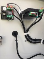
While bringing these various power legs into the enclosure and realizing that I would be providing power to some semi-delicate electronics, my requirement was to ensure for some “clean” power and protection for those electronics. As I stated earlier, I had a requirement for DIN rail mounting. Consequently, I chose to install the two (240VAC and 120VAC) DIN rail mounted devices as listed below to meet this requirement.

SINOTIMER - 240VAC, 40-amp and 120VAC 63-amp, Adjustable Voltage Surge Protector Relays with current/over-current limiting, automatic recovery and voltage/current display features.

Next, I was looking for 240VAC and 120VAC power “cut-off” switches. Based on research, recommendations, reputation and the DIN rail mountable criteria, I looked at “Eaton” products for this requirement.

However, the Eaton cut-off switches were nearly twice as much in price as the Eaton Circuit Breakers (pole protectors). This didn’t make much sense to me but whatever. So, I just purchased and installed the pole protectors and I utilize them as “cut-off” switches. I realize that circuit breakers are not designed or intended for the demanding use of a switch but these will not be getting the type of usage that switches typically get anyway, so they should work just fine. The following is what I selected.

Eaton FAZ-B15-2, Miniature Supplementary 2-pole Protector
Eaton FAZ-B15-1-SP, Miniature Supplementary 1-pole Protector

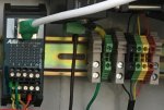
When it came to AC power distribution within the automation enclosure, once again I based my requirements on DIN rail mounting features, research and recommendations. And so I selected the “Dinkle” Assembly type color-coded terminal blocks, for all of my AC power distribution requirements.

To power (and mount) the 120VAC Linksys WAP (because it utilizes the standard two-prong NEMA 1-15 type connector for power), I selected the following module in order to meet my DIN rail mounting requirement.

ASI IMACP01 3-prong AC Outlet Power Module

c) DC Power Requirements and Related Support Equipment

2021-01-03_11-05-39.jpg

Given the fact that much of the electronics within the automation enclosure utilize DC power, I determined that I would require the following Power Supply Units (PSU), to convert the AC power to DC power. I selected the following units based on voltage and amperage requirements, as well as research, recommendations and reputation for quality and reliability.

(1) MEAN WELL EDR-120-5. 5V, 3-amp, 15W PSU. This PSU supplies 5VDC power to the following electronics mounted within the enclosure.​
UPDATE: 1/5/2021 - Sequent Micro-Systems just introduced a NEW Raspberry Pi "Smart" Cooling Fan which appears to be a bit better than the one I selected and referenced here. You can find more information in the following link.​
(2) MEAN WELL EDR-120-5. 12V, 5-amp, 60W PSU. This PSU supplies 12VDC power to the following electronics mounted within the enclosure.​
(3) MEAN WELL EDR-120-5. 24V, 5-amp, 120W PSU. This PSU supplies 24VDC power to the following electronics mounted within the enclosure as well as one peristaltic pump used for automated control of acid dosing.​
2020-12-25_18-05-24.jpg
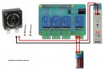
Note: Currently, I am using one of the four relays on this card to control power to the acid peristaltic pump. In doing so, I was advised to incorporate a “Snubber” circuit module for inductive load relay protection. This module should prevent a possible arc between the relay contacts when the contacts open. And which then, might cause the relay to weld shut and thus cause a possible acid pump “runaway” condition.​
Typically, snubber circuits are only needed when relays are being used for an inductive loads such as a motor or coil. After some lengthy discussions and obtaining some sound advice, I selected the following snubber circuit card for my needs.​
The following diagram illustrates the method by which it is installed with regards to the 24VDC PSU, the peristaltic pump and the relay.​
2021-01-02_18-57-16.jpg
Peristaltic Pump (Acid). Pentair PN 522474. Note: This was the peristaltic pump that was originally included with my Pentair IntellipH Acid Dispenser System and which except for this pump and the chemical storage tank, is no longer in use now within my automation system. See the following thread for additional detailed information.​

For DC power distribution, I utilize three (3) each, Electronics-Salon DIN rail mountable 5x3 position pluggable Screw Terminal Block Distribution Modules. One for each (5V, 12V and 24V) PSU’s.


d) Network Connectivity
2020-11-26_19-29-17.jpg
Network connectivity at the equipment pad is provided via a single CAT 5e cable which provides connectivity between a managed network switch at the house and the DIN rail mountable TRENDnet Industrial (un-managed) switch located within this automation enclosure.

Three (3) devices at the pool equipment pad, then share this network connectivity via this network switch. Those devices are listed below.

(1) Pentair IntelliCenter The purpled-colored boot CAT 5e, travels through an interconnected low-voltage flexible conduit and connects to the ethernet port provided for this purpose and which is located on the IntelliCenter Mother Board.​
(2) Raspberry Pi 4B micro-computer located within this enclosure (red colored boot).​
(3) Linksys Wireless Access Point (WAP) located within this enclosure (orange colored boot). This access point does not provide network connectivity for the IntelliCenter. Instead, it merely provides for a stronger Wi-Fi signal for any mobile devices which may be located around the pool equipment pad, as well as for several Wi-Fi enabled and controlled landscape lights that are located nearby.​


e) RS-485 connectivity

2020-11-26_19-30-52.jpgI also had a need to distribute RS-485 connectivity from the IntelliCenter RS-485 bus to the house where the Raspberry Pi micro-computer dedicated for main pool automation and control is located.

In addition, RS-485 connectivity (not from the RS-485 bus), but rather from a test IntelliValve actuator at the equipment pad to another Raspberry Pi computer and which is also located at the house and dedicated for the purpose of IntelliValve actuator testing.

I decided against making these connections within the IntelliCenter Load Center low-voltage compartment. Alternatively, these two connections would be made within my Advanced Automation Enclosure instead. This just made more sense to me. My requirement was again, DIN rail mounting.

For this connectivity requirement, I selected the ASI IMRJ0845 RJ45 Breakout Terminal Block Interface Module.

Serial/RS-485 signals are delivered to this breakout interface module via four Dinkle type terminal blocks just to the right of the module. Those Serial/RS-485 signals originate at the Serial COM Port Expansion Board located on the back wall of the low-voltage compartment of the IntelliCenter OCP Load Center. Transmission is accomplished via a 4-conductor cable which is ran within the provided flexible conduit between the low-voltage raceway of the load center and this enclosure.
IMG_6012.JPG
RS-485 connectivity is then delivered to those two (2) Raspberry Pi 4B micro-computers at the house via the CAT 5e cable plugged into the Interface Module (green RJ-45 boot).

The test IntelliValve actuator, RS-485 signal is connected to one of those Raspberry Pi computers dedicated for that purpose. That signal is “highjacked” in the Intermediate / Feeder Low-Voltage Junction box and delivered to the interface module instead of connecting it to the actual IntelliCenter RS-485 bus like the other five IntelliValve actuators that are part of my overall system do.

The RS-485 signal from the IntelliCenter RS-485 bus is delivered to the second Raspberry Pi micro-computer at the house and which is dedicated for nodejs-poolController-dashPanel pool automation and control.


Enclosure - Major Component “Break-down”

2021-01-03_11-32-11.jpg

Warning: Typically I always provide a warning at the end of any discussions or threads that I contribute to, which reference the installation of electrical components and/or swimming pool electrical work. I make no exception here.

If you are considering a similar project and you are not qualified or do not possess the skill sets necessary to safely perform pool electrical planning and work. Then PLEASE… consult with a qualified pool electrician who does possess those skills.

(Continued in next post)
 
Last edited:
4. Sensors, Probes, EZO Circuits and Hosts

2020-12-05_07-50-41.jpg

a) Overview


After months of discussions, research and receiving various recommendations. I examined several options regarding applicable and various sensors and probes. I decided to incorporate the Atlas Scientific Environmental Robotics, “Industrial” line of sensors and probes for those requirements. My reasoning for this decision is explored in detail below.

There were some recommendations from other members here that already had some exposure and experience with this line and so that weighed heavy on my decision-making process. When looking at the reputations of different manufactures and their sensors and probes, one factor that also had me leaning towards Atlas Scientific was customer support and technical assistance.

After a couple of pre-sales consultations with their technical support team, I knew this company was the way to go for me and I would find that reasoning to be confirmed later on, during my initial setup.

Compatibility as well as expandability were other key factors for me. In other words, I wanted all the sensors/probes as well as the “host” boards to “play-nice” with one another. Not unlike when one is advised here to utilize all Pentair equipment or all Hayward equipment for instance, when planning for pool automation. I used that very same principle here to select my sensors, probes, host boards, etc.

Another requirement that I looked at here, was that of the communication protocols involved. I selected sensors/probes/circuits and boards that would support the Inter-Integrated-Circuit (I2C) communication protocol.

I2C is a synchronous, multi-master, multi-slave, packet switched, single-ended, serial communication protocol typically utilized on an I2C bus.

Invented in 1982 by Philips Semiconductor, it is widely used for attaching lower-speed peripheral ICs to processors and microcontrollers in short-distance, intra-board communication scenarios not unlike the very application found here.

This requirement was purely based on recommendations and internet research and the fact that REM would indeed support the I2C protocol.


b) Sensors and Probes

Note
: Again, there are different manufactures of sensors, probes and hosts. However, I will discuss those that I selected based on my own research and recommendations received.

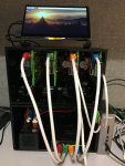
I am currently utilizing seven (7) sensors/probes that are connected semi-directly, via terminal boards mounted in junction boxes, to their respective Atlas Scientific “Electrically Isolated” EZO Circuits. The circuits are then “hosted” by a total of two (2) each Whitebox Stackable Tentacle T3 “sensor host” add-on boards or otherwise known as “shields.”
The Tentacle T3 stackable shields connect and “mount” if you will, to the Raspberry Pi micro-computer via its GPIO pins. After which the EZO circuits and sensors/probes, connect to the shield. This shield eliminates the need for additional wiring, multiplexing and electrical isolation.

User interaction with the sensors can then be accomplished through REM, the Atlas Scientific IoT Monitoring Software or lastly by utilizing the Raspian Command Line Interface (CLI).

2020-12-04_18-56-56.jpg
Tentacle T3 stackable shields for the Raspberry Pi, can host up to five (5), EZO-class devices each. These devices can support and/or measure and report pH, ORP, Conductivity (Salt Level), peristaltic type pumps used for controlled chemical dosing (acid and liquid chlorine), pressure sensors (filter pressure), temperature, humidity, dew point and much more.

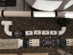
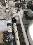
In my case, three sensors (EC, pH and ORP) are located and “plumbed-in” within a “Sensor Bypass Manifold,” which is located in-line between the pool filter and the heater bypass 3-way valve. This sensor bypass manifold is examined in more detail in Section 5 c), below.

As mentioned above, I selected the Industrial line of Atlas Scientific sensors/probes for my requirements. However, there are other Atlas Scientific product lines of sensors/probes as well. These include their “Lab Grade” and “Consumer Grade” lines.

Note: For those that reside in the colder climates, consideration should be given to disconnecting and removing probes from pool plumbing systems in the winter. When doing so, pH and ORP sensor/probes should be stored with their caps and within the appropriate storage solutions.

The sensors/probes that I selected and related/detailed information are explored in further detail below:
2020-12-29_15-03-05.jpg
Conductivity (EC) - Measures the “electrical conductivity” in the pool water. The result of this measurement is calculated and can be displayed in microSiemens (µS), Dissolved Solids (ppm), Salt Level (ppm) and Specific Gravity (sp). H2O temperature is also provided in degrees Celsius.

Note: If anyone is considering this same sensor/probe. PLEASE ensure that you purchase the “K 1.0” model and NOT the K 0.1 model. The K 0.1 model is the wrong sensor for swimming pool E.C. sensor applications.

This sensor/probe is “plumbed-in” and located in the Sensor Bypass Manifold.

2020-12-04_19-03-17.jpg
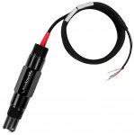
pH (Potential Hydrogen) – Determines acidity or alkalinity of the water and should be self-explanatory to most here. If not, then please refer to the TFP Pool School for more information on pH. The result of this measurement is of course output in a standard reading of pH. H2O temperature reading in degrees Celsius is also provided.

This sensor/probe is “plumbed-in” and located in the Sensor Bypass Manifold.

NOTE: pH probe tips MUST always stay wet or at least moist and should never be allowed to dry out. As long as they are installed within a closed loop pool plumbing system, there is enough moisture within the pipes to keep the probe tip moist.


2020-12-05_08-38-31.jpg
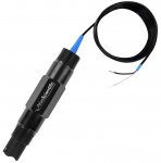
ORP (Oxidation Reduction Potential) - Without all the chemistry explanations that would typically be appropriate and applicable here. Simply put, ORP is a measurement of the sanitizer effectiveness of the water. However, that simple explanation can be VERY deceiving unless one understands that there are a great many variables that actually affect ORP values.

Now, if you’re preparing to launch a “radar-guided missile” my way because I am utilizing an ORP sensor, maintain a current CYA level well over 30 and utilize a SWCG for chlorine production. Well don’t. :p

Or at least “check fire,” until you have thoroughly read my three notes below. After that, if you’re just determined to remain in target acquisition mode, then “LOCK ON” and press FIRE. I have more than an adequate amount of fully loaded chaff dispensers on-board. ;)

Note 1: I will not use this thread to provide an in-depth discussion of ORP. There are mountains of material found throughout TFP related to ORP. Generally, the use of ORP readings for chlorine management are ill-advised on TFP. Especially, given the fact that sole reliance on an ORP value is contradictory in many cases to the “tried-and-true” TFP method of pool care.

Note 2: I support and adhere to this method of pool care presently and I practice it nearly religiously. If you don’t believe me, then please refer to my TFP PoolMath Logs. My free chlorine (FC) level is determined by utilizing a TF-100 Pool Test Kit and I’m not planning on changing that methodology anytime in the foreseeable future and notwithstanding future developments such as experimenting with much lower CYA levels. This is due to the fact that higher CYA levels can result in deceiving ORP values.

Note 3: I added an ORP sensor mostly out of a sense of both curiosity and for “experimentation sake” at this point. To quote a well-known movie - I wanted to see “what all the hub-bub was about.” Especially from the Europeans. My CYA level is about 70. And so based on that fact, I have determined that it would not be wise to solely rely on an ORP reading at this time to make adjustments to my IntelliChlor SWCG. So just call me “guinea pig.” Others do.

This sensor/probe is “plumbed-in” and located in the Sensor Bypass Manifold.

NOTE: ORP probe tips MUST always stay wet or at least moist and should never be allowed to dry out. As long as they are installed within a closed loop pool plumbing system, there is enough moisture within the pipes to keep the probe tip moist.

H2O Temp – This temperature reading can be provided to an EZO RTD Circuit, via either the pH probe or in my case, the EC probe. Temperature can be reported in both Celsius or Fahrenheit.
2020-12-05_08-40-46.jpg
Free Air Temp (FAT) – This sensor (PT1000) was fairly inexpensive and provides for a redundant as well as comparative device for the Pentair FAT sensor. So far, I have found this sensor to be slightly more accurate than the Pentair FAT sensor. Temperature can be reported in both Celsius or Fahrenheit.

This sensor is mounted on the lower outer deck of my new automation enclosure and utilizes the 30mm Temperature Thermowell for mounting purposes.


2020-12-05_08-42-14.jpg
Humidity – I couldn’t resist adding this sensor into the “mix”. Especially since the “price was right.”

Actually, it’s kind of nice to have. However, this little sensor does quite a bit more as was discovered by @rstrouse. He was kind enough to include this sensor output into the REM software by using my “HUM” sensor as a test bed for its code development.

Not only does it report humidity as a percentage (of course), but it also reports “dewpoint” in either Celsius or Fahrenheit. In addition, we found that it reports FAT as well, in either Celsius or Fahrenheit.

As like theIMG_6260.JPG FAT sensor referenced above, this sensor is mounted on the lower outer deck of my new automation enclosure.

Note: Through some comparative testing and analysis that I performed utilizing my hand-held scientific thermometer. I have actually found this sensor (humidity), to report the most accurate FAT readings out of the three FAT sensors that I have now accumulated (Pentair FAT sensor, Atlas Scientific FAT (RTD) sensor and the Atlas Scientific Humidity Sensor). Consequently, I have made the FAT readings from the Humidity Sensor as the baseline for calibrating FAT readings for the other two devices.


2020-12-05_08-43-51.jpg
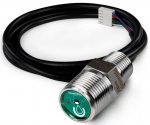
Pressure – This sensor is mounted to my pool filter utilizing a ¼” NPT “Y” adapter. By doing so, I can still maintain the analog gauge mounted on the filter but I can also provide for mounting this pressure transducer as well.

Yes, this sensor provides filter pressure readings and appears to be very accurate.

These filter pressure readings can be reported in any of the following reporting units:

Pounds per Square Inch (psi) which is the typical “standard” for pool filters in the U.S.

However, if one may have other preferences. Then they can indulge themselves in the many other available reporting units as well. And which are listed below.

Atmospheric Units (atm)
Metric Pressure (bar)
Kilo-Pascals (kPa)


There are other Atlas Scientific sensors available as well, however, the following listed sensors are really not applicable for pool automation or control use. These sensors include DO, CO2, Oxygen and Color Sensors.

However, there are two other Atlas Scientific devices that are indeed applicable to pool automation or control use. One of them is the variety of Atlas Scientific flow meters to include their newer embedded “Flow Meter/Totalizer”.

2020-12-05_08-48-58.jpg
In addition, they manufacturer a very cool looking (and smart) embedded dosing pump that I may incorporate at some point into my automation mix if I ever have any issues with my current peristaltic pump.

Lastly, if Atlas Scientific ever decides to manufacture and market a truly reliable Amperometric Chlorine Sensor and if it is NOT cost-prohibitive, then “I’m in." It has been rumored that this may be “in the works.”

(Continued in next post)
 
Last edited:
c) Sensor/Probe Mounting Considerations

2020-11-29_16-48-15.jpg

I came to realize that after quite a bit of research and discussions on the topic of sensor/probe mounting, that the predominate thinking is that a sensor bypass line or “manifold” should be utilized. This can also include an item known as a “flow cell manifold”. Different deal, same purpose.

The primary reason for this bypass manifold, is that it allows for flow reduction of water past the sensors so that sensors/probes are not damaged. However, Atlas Scientific has assured me that the Industrial line of probes can withstand a flow rate in excess of 100gpm.

Additionally, a bypass manifold, incorporating a 3-way valve “upstream” and a check valve “downstream” allows for the “servicing” of the sensors/probes, without ever having to completely shut down the pool filtration system.

Hence, I decided that a sensor bypass manifold should be incorporated within my pool plumbing.

The ability to plumb in a sensor bypass manifold within an existing plumbing setup may present quite a challenge to many. Every case is different. In my case, I was able to “dodge that bullet” to a certain extent.

This was due in part to the fact that - in my return line between the filter multi-port valve and the heater bypass valve, I had incorporated two union fittings when I upgraded/plumbed the equipment pad last. This fact allowed me to remove the line and then somewhat easily modify it to support the inclusion of a sensor bypass manifold.

I utilize a Jandy 3-way valve to manually adjust water flow through the bypass line.

Three of the tees (2 through 4), for sensor mounting are the 2”s x 2”s x ¾”t type. One each for ORP and pH and one spare. The spare is an attempt by me to provide a little bit of “future proofing” here, as modifying existing pool plumbing lines is really NOT all that much fun!

Note: Currently, I am planning on mounting a Flow Sensor in that last tee that does not have a sensor/probe mounted in it. Consequently, if water flow through the manifold is ever inhibited for any reason, I will be alerted and chemical dosing will cease until such time as the situation has been resolved. Just another level of redundancy.

2020-12-05_16-43-07.jpg
The first of the four tees is a 2”s x 2”s x ¾”s type. This was because the Industrial EC probe comes permanently mounted using a ¾” slip union type fitting. Since the schedule 80 ¾” union that comes with the Industrial probe uses a ¾” tee, I had to purchase a second schedule 80 ¾” slip union, so I could glue the bottom part of the union onto my 2” tee. That worked out well, since when EC sensor calibrations are performed, it’s recommended they be done in a tee according to the documentation. So now I have that ¾” tee which is attached to the bottom half of the union, stowed away in a drawer and intended for just that purpose.

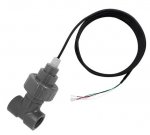
You really don’t need to install a FlowVis Flow Meter in the bypass line, as I had done. But I required a “check valve” of some type, downstream anyway. So I just went with a FlowVis. Who said that check valves, can’t be sexy? The FlowVis was originally intended to measure the water flow past the sensors. However, I find the sight glass fairly handy though, as I can visually approximate the water flow past the sensors using the sight glass. However, a clear Schedule 80 “fitting” just upstream from the check valve should suffice just as well here. I do realize that a FlowVis Flow Meter can induce some back pressure to water flow but in this application, it’s negligible.

IMG_6238.JPG
NOTE: I encountered quite the unexpected issue when performing a quick “test fit” of the pH probe into one of the tees during manifold construction. IT DIDN’T GO ALL THE WAY DOWN INTO THE TEE FITTING!

After consultations with two other TFP members regarding this situation. I came to find out that some types of tees have too much PVC at the bottom of the threads within a SxSxT type tee. This fact prevents the sensor head from protruding down far enough past those threads in order to seat properly and to allow the sensor tip to protrude further into the fitting. Who would have thought?

In my case, I had to perform some delicate “surgery” on the inner bottom portion of three tee’s. Carefully using a Dremel Tool to hollow out and widen this area. I say “carefully” because thread damage was a concern to me here. This surgery was ultimately successful, but it was a real “pain” if you know what I mean.

It seems that @Katodude had encountered this similar type of problem with his Atlas Scientific Industrial pH probe and reported having to do some “whittling” on his tee fitting as well.

@cmc0619 experienced a similar encounter. He even produced a couple of videos to explain this problem. These videos can be found below.


@cmc0619 suggests that others who may be considering a similar project understand the following: they may want to seriously consider using “BSP/BSPT threaded tees” for the screw connections (no changes in the SLIP sides of the fittings). You can find them at various vendors on the web with various sizes.

FlexPVC has a good assortment. Then you have no Dremel work to do, they just screw right on.

In retrospect, had I known about this “anomaly” beforehand, I would have taken this alternative course to prevent this encounter. “Live and learn.”


d) Initial Sensor Setup and Configuration

After some pre-sales consultations with Atlas Scientific, I proceeded to order my sensors and probes as well as the applicable and necessary EZO circuits and two (2) Tentacle T3 shields.
Once my order IMG_6233.JPGarrived and after studying the online documentation, it was now time for some initial setup. I mounted the T3 boards to the Raspberry Pi micro-computer. I had previously configured the Raspberry Pi for this use, to include the necessary I2C configurations, etc.

The following links are made available to help facilitate the setup of the Raspberry Pi micro-computer, the Tentacle T3’s as well as the EZO circuit setup.

The link directly below, is a great “instructable” for connecting multiple sensors to a Raspberry Pi using a Tentacle T3 Shield.


Tentacle T3 for Raspberry Pi Quick Start Guide

The EZO circuits are mounted to the Tentacle T3 shields via four connector pins.

NOTE: I highly recommend the purchase and use of the Atlas Scientific I2C Toggler. The I2C Toggler is a tool designed for the easy switching of the protocol type of an EZO circuit from UART to I2C by a simple press of a button. Best eleven bucks I ever spent!

2020-12-10_19-41-51.jpg
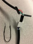
However, the pressure (PRS) and humidity (HUM) sensors cannot utilize this toggler, so they will still require the “old-fashioned,” manual switching method from UART to I2C. This is done by using a jumper wire. Atlas Scientific will be more than happy to walk you through the procedure as they did with me.

Note: All EZO circuits should indicate solid blue (not blinking) status lights at this time. This will indicate that the circuits have been successfully toggled from UART to I2C. If any of them are not solid blue, then perform the UART to I2C conversion again until they are.

Once the Raspberry Pi and the hardware have been fully prepared and configured. You should now be able to see all of your I2C configured devices utilizing the following command within the Raspian CLI.

sudo i2cdetect -y 1

As an example, the devices listed on line 60 in the screen capture below, are my various Atlas Scientific circuits. The device located at 30f (3f), is my Sequent Microsystems I2C 4-relay Card and on line 50 is my Sequent Microsystems Industrial I2C Automation Card.

2020-11-26_19-38-10.jpg

NOTE: There is no need to actually have the sensors connected to the T3 shields at this point. Only the EZO circuit(s).

Sensor wiring connectivity to the Tentacle T3 shields is accomplished in most cases through the use of female BNC to terminal screw adapters which then screw connect to the Tentacle T3 shields.

Once this is accomplished , then you can proceed with REM setup and configuration.

Note: If you are planning on utilizing Atlas Scientific sensors and probes but do not plan on incorporating these with REM and/or nodejs-poolController or nodejs-poolController-dashPanel, then you have the option of using the Atlas Scientific IoT Professional Water Monitoring System for Raspberry Pi computers, as mentioned in Section 4. b) above.

Remember, you’ll still need a Raspberry Pi micro-computer for mounting and running the Tentacle T3 boards anyway. So, you might as well download, install and incorporate nodejs-poolController, nodejs-poolController-dashPanel and REM. Especially if you are utilizing Pentair Automation.

I don’t necessarily advocate the use of the Atlas Scientific IoT Monitoring System due to what I found to be limitations and the lack of compatibility for my purposes. Attempting to run the IoT software concurrently with REM will NOT work.

However, I have provided some information on its use in the event that someone is just looking for a pool water monitoring capability, and is not looking for sensor integration with nodejs-poolController / nodejs-poolController-dashPanel. More information on the Atlas Scientific IoT Monitoring Software can be found it Section 5. b) below.

(Continued in next post)
 
Last edited:
  • Love
Reactions: cmc0619
5. Additional Miscellaneous Information

2020-12-05_12-50-21.jpg

a) Calibrations

Note 1
: Atlas Scientific sensors/probes come “pre-calibrated” from their factory. HOWEVER, it is recommended by their technical support staff that sensors/probes be calibrated along with the particular EZO Circuit Chip that will be paired with the sensor/probe. Doing so, will apparently, provide for a more precise reading in the end according to Atlas Scientific.

Abbreviated calibration instructions are provided on the applicable REM device windows and should be adequate for many end-users.

During my testing, I personally found calibrations performed in REM, “superior in use,” compared to the IoT Monitoring Software. Several “accommodations” and calibration improvements for the user have been applied by the developer of REM.

In the sections below, I will attempt to provide detailed calibration steps since I cannot find other sources for Atlas Scientific Sensor/Probe calibrations in as much detail.

Note 2: You might want to keep this in mind when it comes to calibrations. The more “scientifically” that you approach the task of calibrations with, the more accurate those calibrations will be. The more accurate the calibrations, the more accurate your pool water sensor readings will be. Just common sense.

Note 3: The calibration instructions as outlined below utilize REM, as the calibration software platform and are the results of my personal experiences.

Note 4: Atlas Scientific markets all of the necessary calibration solutions that will be needed when performing calibrations on their sensors/probes as provided for in the following link.

Atlas Scientific EZO-EC Calibration Procedure

Note: I will list the detailed steps for a Two Point EC Calibration. Upon reviewing the Two Point Calibration steps, a Single-Point Calibration procedure should be relatively - self-explanatory.

1. Prepare your computer. REM should be on your screen and you should be in the Atlas EZO-EC device screen. You can also do this on a touchscreen monitor at the pad or use a tablet.

2. Warm (or chill) the calibration solutions to 25 degrees C. (or as close as you can). I used a hand-held type scientific thermometer to accomplish this task. This step helps to eliminate the use of the temperature compensation charts during calibration since the EZO conductivity circuit has its temperatures set to 25 degrees C by default.

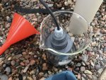
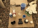
3. Gather your materials and head to the pool equipment pad. You will need the following materials as indicated below and illustrated in the photos below.
IMG_6303.JPG
a) The two (2) calibration solutions.
Note: The calibration solution kit utilized for the K1.O EC calibrations should be the Conductivity Calibration K1.0 (chem-IEC-1.0) 1,413uS and 12,800uS.

b) A separate ¾” tee with slip-union and cap as shown in the photo.

c) A glass beaker large enough for the tee to fit inside but not too wide. Note: If the beaker is too wide, then the level of calibration solution will not be high enough in the beaker to cover the sensors.

d) a small funnel.

f) Container of tap water (approximately 2-4 cups or so).

g) Clean paper towels.

IMG_6306.JPG

4. Perform a dry EC calibration. This is a necessary part of the EC calibration process and must be completed prior to any single-point or two-point EC calibration.
2020-12-05_13-33-03.jpg
a) Remove the probe from the fitting in the manifold by unscrewing the union and lifting up.

b) Replace the top part of the EC Calibration union that has the cap attached. This will prevent a large amount of air into your plumbing system and keep most of the water in your filter from draining down and will prevent your pump from having to work so hard to re-prime.

c) Gently shake the water off of the probe and pat dry. The idea here is to remove any water on and around the two probes that make up the EC Sensor. Lightly run your paper towel in between the two probes.

d) Just place your probe on something clean or hang on one of the plumbing pipes etc. Just don’t put it down on anything that could interfere with the calibration. The probe should be in the air.

e) On your computer, click or tap Clear in the Calibration pane. This will clear any previous calibrations from the sensor.

f) Click or tap the Suspend Temperature Feed checkbox. This step also helps to eliminate the use of the temperature compensation charts during calibration since the EZO conductivity circuit has its temperatures set to 25 degrees C by default.

g) Also in the Calibration pane, click or tap the Setpoint pulldown and select Dry.

h) Click or tap Calibrate. You should see mostly zero’s in the Readings pane and see “True” appear next to “Dry” in the Device Info pane.


5. Perform a low EC calibration
2020-12-05_13-39-11.jpg
a) At the equipment pad, pour the low calibration solution into your beaker.

b) Place the probe in the bottom half of your EC calibration union (with the tee attached).

c) Place the probe/union/tee configuration in the beaker of low calibration solution. Ensure all air that may be trapped in the tee are eliminated by tipping the beaker slightly towards one of the openings of the tee.

d) Allow the reading to stabilize for a couple of minutes. Conductivity indications may be as much as 40% different from that of the calibration solution.

e) In the Calibration pane, click or tap the Setpoint pulldown and select Low.

f) Click or tap Calibrate. You should now see the low reading appear in the Device Info pane.


6. Perform a HIGH EC calibration
2020-12-29_15-37-28.jpg

a) At the equipment pad, remove the probe/union/tee configuration from the beaker.

b) Remove the probe from the tee configuration and rinse with the tap water and pat the probe dry. Rinse the tee and dry.

c) Using a clean and dry funnel, pour the low calibration solution in the beaker, back into its bottle and cap.

d) Rinse the beaker with tap water and dry.

e) Place the probe back into the bottom half of your EC calibration union (with the tee attached).

f) pour the HIGH calibration solution into your beaker.

IMG_6305.JPG
g) Place the probe/union/tee configuration in the beaker of high calibration solution. Ensure all air that may be trapped in the tee are eliminated by tipping the beaker slightly towards one of the openings of the tee.
h) Allow the reading to stabilize for a couple of minutes. Conductivity indications may be as much as 40% different from that of the calibration solution.

i) In the Calibration pane, click or tap the Setpoint pulldown and select High.

j) Click or tap Calibrate. You should now see the high reading appear in the Device Info pane.


7. Completion: You have now completed the EC calibration procedure for the most part.

a) At the equipment pad, remove the probe/union/tee configuration from the beaker.

b) Remove the probe from the tee configuration and rinse with the tap water.

c) Using a clean and dry funnel, pour the high calibration solution in the beaker, back into its bottle and cap.

d) Remove the top part of the EC Calibration union that has the cap attached, from your sensor manifold.

e) Replace the EC probe back into your sensor manifold.

f) Turn pump on medium speed.

g) Open the sensor manifold 3-way valve 100%. This will eliminate air in the sensor manifold.

h) Adjust sensor manifold 3-way valve to normal setting.

i) Open filter petcock to eliminate air within the plumbing system.

j) Turn pump off.

k) At your computer, uncheck the Suspend Temperature Feed checkbox. Your EC readings should be accurate and normal at this time. Under Calibration Points in the Device Info block, you should see “True” next to Dry and the correct calibration numbers for the applicable points. In addition, you should see the applicable number of Calibrated Points in the Calibration block.

Note: EC calibrations should rarely be needed if ever again and mostly, just in case you feel that the readings obtained from the EC sensor are no longer valid or normal.


Atlas Scientific EZO-PH Calibration Procedure

Note: The most important part of pH calibration is watching the readings during the calibration process.

2020-12-05_13-41-16.jpgThe Atlas EZO pH circuit has a flexible calibration protocol, allowing for single-point, two-point or three-point calibration. If this is the first-time calibrating the EZO pH circuit, it is recommended that you calibrate in the following order:

Mid-point (pH 7) --> Low point (pH 4) --> High point (pH 10)

Two-point calibration will provide high accuracy between 7.00 and the second point calibrated against such as 4.00. Three-point calibration will provide high accuracy over the full pH range. Three-point calibration at 4.00, 7.00 and 10.00 should be considered the standard.

Doing a mid-point calibration after the pH circuit has been calibrated will clear the other calibration points. Hence the mid-point must be done first.

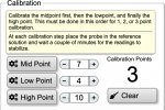
1. Prepare your computer. REM should be on your screen and you should be in the Atlas EZO-pH device screen. You can also do this on a touchscreen monitor at the pad or use a tablet. Click the Clear button. This will clear the previous pH calibration.

2. Warm (or chill) the calibration solutions to 25 degrees C. (or as close as you can). I used a hand-held type scientific thermometer to accomplish this task. This step helps to eliminate the use of the temperature compensation charts during calibration since the pH circuit has its temperatures set to 25 degrees C by default.

3. Gather your materials and head to the pool equipment pad. You will need the following materials as indicated below and illustrated in the photos below.
a) The three (3) calibration solutions.

b) A glass beaker.

c) a small funnel.

d) Container of tap water (approximately 2-4 cups or so).

e) Clean paper towels.

4. Perform a mid-point (7.0) pH calibration.

a) Remove the probe from the fitting in the manifold by unscrewing it and lifting up.

b) Gently shake the water off of the probe and pat dry. The idea here is to remove any water on and around the probe tip and so as to not dilute the calibration solution.

c) Pour the pH 7.0 (yellow) calibration solution in the beaker and place the pH probe in the solution. Stir around slightly to ensure all air bubbles have been eliminated.

d) Allow the probe to remain in the solution and watch the pH numbers on the screen.

e) When the numbers have stabilized for the most part, select 7 in the Mid Point window and click the Mid Point button.

f) Remove the probe from the calibration solution and rinse.

g) Using a clean and dry funnel, pour the mid-point calibration solution in the beaker, back into its bottle and cap.

h) rinse the beaker with tap water and dry.


5. Perform a low-point (4.0) pH calibration.

a) Pour the pH 4.0 (red) calibration solution in the beaker and place the pH probe in the solution. Stir around slightly to ensure all air bubbles have been eliminated.

b) Allow the probe to remain in the solution and watch the pH numbers on the screen.

c) When the numbers have stabilized for the most part, select 4 in the Low Point window and click the Low Point button.

d) Remove the probe from the calibration solution and rinse.

e) Using a clean and dry funnel, pour the mid-point calibration solution in the beaker, back into its bottle and cap.

f) rinse the beaker with tap water and dry.


6. Perform a high-point (10.0) pH calibration.

a) Pour the pH 10.0 (blue) calibration solution in the beaker and place the pH probe in the solution. Stir around slightly to ensure all air bubbles have been eliminated.

b) Allow the probe to remain in the solution and watch the pH numbers on the screen.

c) When the numbers have stabilized for the most part, select 10 in the High Point window and click the High Point button.

d) Remove the probe from the calibration solution and rinse.

e) Using a clean and dry funnel, pour the mid-point calibration solution in the beaker, back into its bottle and cap.

f) rinse the beaker with tap water and dry.


7. Completion: You have now completed the pH calibration procedure for the most part.

a) At the equipment pad, replace the EC probe back into your sensor manifold.

b) Turn pump on medium speed.

c) Open the sensor manifold 3-way valve 100%. This will eliminate air in the sensor manifold.

d) Adjust sensor manifold 3-way valve to normal setting.

e) Open filter petcock to eliminate air within the plumbing system.

f) Turn pump off.

g) At your computer, you should see the applicable number of Calibrated Points in the Calibration block.


Atlas Scientific EZO-ORP Calibration Procedure

Note: The Atlas EZO ORP (oxidation-reduction potential) circuit has a flexible calibration protocol, allowing single point calibration to any off the shelf calibration solution. However, if this is your first time calibrating the EZO ORP circuit, Atlas Scientific recommends using the 225mV calibration solution.

1. Prepare your computer. REM should be on your screen and you should be in the Atlas EZO-ORP device screen. You can also do this on a touchscreen monitor at the pad or use a tablet. Click the Clear button. This will clear the previous ORP calibration.

2. Warm (or chill) the calibration solutions to 25 degrees C. (or as close as you can). I used a hand-held type scientific thermometer to accomplish this task. This step helps in the precision of the calibration since the ORP circuit has its temperatures set to 25 degrees C by default.

3. Gather your materials and head to the pool equipment pad. You will need the following materials as indicated below and illustrated in the photos below.

a) The ORP calibration solution.

b) A glass beaker.

c) a small funnel.

d) Container of tap water (approximately 2-4 cups or so).

e) Clean paper towels.


4. Perform a ORP calibration.

a) Remove the probe from the fitting in the manifold by unscrewing it and lifting up.

b) Gently shake the water off of the probe and pat dry. The idea here is to remove any water on and around the probe tip and so as to not dilute the calibration solution.

c) Pour the 225mV calibration solution in the beaker and place the ORP probe in the solution. Stir around slightly to ensure all air bubbles have been eliminated.

d) Allow the probe to remain in the solution and watch the pH numbers on the screen.

e) When the numbers have stabilized for the most part, select 225 mV in the window and click the Calibrate button.

f) Remove the probe from the calibration solution and rinse.

g) Using a clean and dry funnel, pour the ORP calibration solution in the beaker, back into its bottle and cap.

h) rinse the beaker with tap water and dry.


5. Completion: You have now completed the pH calibration procedure for the most part.

a) At the equipment pad, replace the ORP probe back into your sensor manifold.

b) Turn pump on medium speed.

c) Open the sensor manifold 3-way valve 100%. This will eliminate air in the sensor manifold.

d) Adjust sensor manifold 3-way valve to normal setting.

e) Open filter petcock to eliminate air within the plumbing system.

f) Turn pump off.


Atlas Scientific EZO-RTD (Temperature) Calibration Procedure

NOTE: This one is the easiest.


1. Prepare your computer. REM should be on your screen and you should be in the Atlas EZO-RTD device screen. You can also do this on a touchscreen monitor at the pad or use a tablet. Click the Clear button. This will clear the previous RTD (temp) calibration.

2. Using a hand-held scientific thermometer, place the thermometer probe in the close vicinity of the RTD probe and allow the number to stabilize.

3. When the numbers have stabilized for the most part, select the number shown on the thermometer in the window and click the Calibrate button.

4. You’re done. You should see True” below the word “Calibrate”.


(Continued in next post)
 
Last edited:
  • Love
Reactions: cmc0619
b) Atlas Scientific IoT Monitoring Software

IMG_6298.JPG
There are two variations of the Atlas Scientific IoT Monitoring Software available on the Atlas Scientific website. There is the Atlas IoT (Windows 10) Dashboard (Not compatible with Mac). And then there is the Atlas Scientific IoT Core which is ran directly on a Raspberry Pi micro-computer. Hence, if you are using a Mac, then you can just SSH from your Mac directly into the Raspberry Pi.

Initially I tried the Atlas Scientific IoT Monitoring Software out and it’s kind of cool. It has some colorful graphics and fairly good “graphing” capabilities and it can be connected to the cloud via MQTT.

However I found it lacking in quite a bit of detail compared to REM and it does not integrate with the nodejs-poolController, so it is not for me. There are issues that I have found with the IoT software but to be fair, I understand that it is under continued development so it should continue to improve.

However, I will not discuss the IoT monitoring system here because I chose to use REM and the nodejs-poolController and nodejs-poolController-dashPanel instead. Mainly because I was already running that system and the fact that I really like the overall concept and the platform and I believe that the IoT monitoring system still has a way to go to be as solid as I think it should be.

It you just want to use the IoT software, then pertinent information can be found in the following links and it should be noted that if you have any issues with installation of this software, the Atlas Scientific Tech Support Team will be more than happy to assist you. I really found them to be quite phenomenal when it comes to technical support.


c) Other Atlas Scientific Kits

Two other Atlas Scientific monitoring kits exists which may have potential for swimming pool applications. These may deserve further exploration depending on the user’s own particular computer/software setup and requirements as well as what type of automation integration they are contemplating.

These are the Wi-Fi Pool Kit and the Industrial Monitoring Kit as listed below. Consultations with the Atlas Scientific Technical Support staff is advised.


Note: Additional miscellaneous information will be inserted here as it becomes available.


6. Useful References and Links -


7. Glossary

Inter-Integrated-Circuit
(I2C)

I2C is a synchronous, multi-master, multi-slave, packet switched, single-ended, serial communication protocol typically utilized on an I2C bus.

Invented in 1982 by Philips Semiconductor, it is widely used for attaching lower-speed peripheral ICs to processors and microcontrollers in short-distance, intra-board communication scenarios not unlike this very same application.


OCP - Outdoor Control Panel. For many, this term is used synonymously with a Pentair Automation Panel. However, in the expanded context of this discussion, it could also represent a different manufacturer and/or a homemade or “DIY” controller as well.

nodejs-poolController - nodejs-poolController is an application to communicate with and control your various pool equipment. The nodejs-poolController will not only function with and control the Pentair IntelliCenter but it is fully compatible with the Pentair IntelliTouch and Pentair EasyTouch automation systems as well. In fact, the nodejs-poolController actually adds capabilities that do not currently exist with the IntelliTouch/EasyTouch control boards as well as most other web clients.

NOTE: The nodejs-poolController can be utilized to control DIY/"Home-Brew" pool automation systems as well.


nodejs-poolController-dashPanel - nodejs-poolController-dashPanel is a controller designed to operate using the nodejs-poolController server backend. You will need to set up your nodejs-poolController server and have it communicating with your pool equipment prior to setting up the dashPanel. Once you have done that you can set up the dashPanel to communicate with the nodejs-poolController server.

While the dashPanel was originally developed using an IntelliCenter control panel, it should operate equally well with an IntelliTouch or EasyTouch control panel.


REM – REM is the abbreviation for “relayEquipmentManager.” It was originally developed and intended - to allow for other types of relays (besides the relays contained within Pentair automation panels), to be controlled. However, in a short period of time. This software has recently morphed into much more than was originally intended.

The relayEquipmentManager (REM) is a fully functional sensor and chemical controller that allows for “Serial Peripheral Interfacing” (SPI) and will support "Inter-Integrated Circuit" (I2C) functionality for external sensors related to pool automation and control.

With regards to relays, currently REM will allow for as many valve or other relays as one has available GPIO pins. That sensor information is then fed over SPI. The advantage here is ease of configuration and with no additional programming required. Another major advantage, is the fact that REM will communicate with the nodejs-poolController via the socket interface.

Note: REM is in the final stages of initial development and is currently in beta testing. Once that beta testing is complete, the software will be released by the developer.

Serial Peripheral Interface (SPI). SPI is a synchronous serial communication interface specification used for short-distance communication, primarily in embedded systems.

The interface was developed by Motorola in the mid-1980s and has become a de facto standard. Typical applications include Secure Digital cards and liquid crystal displays.

(Continued in next post)
 
Last edited:
  • Love
Reactions: cmc0619
8. Additional Photographs with Related Comments

This last post simply contains some representative photos taken during various phases of this project and with a few applicable comments.

Initial test fit of the enclosure at the pool equipment pad. A long way to go.
IMG_6167.JPG

Building out the enclosure fans thermostat control and mounting.

IMG_6183.JPG

Let there be power…
IMG_6178.JPG

First run of nodejs-poolController-dashPanel at the equipment pad.
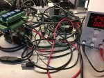
IMG_6259.JPG


For me – The setup, configuration and initial testing is always easier on a “test-bench.” In this case, my office.
IMG_6268.JPG

Initial layout for the Sensor Bypass Manifold.
IMG_6267.JPG


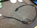
Modification of the Filter Pressure Transducer cable.
IMG_6272.JPG

Installation of the newly completed Sensor Bypass Manifold into the plumbing system.
IMG_6323.JPG

Testing the Filter Pressure Transducer.
IMG_6291.JPG

Nodejs-poolController-dashPanel and REM side-by-side on the equipment pad monitor. Not integrated at this point.
IMG_6321.JPG

r.
 
Last edited:
This is great!

Any idea how often the ORP and pH sensors will require recalibration? I've convinced myself that doing something like this wasn't worth it due to the sensors falling out of calibration .. but maybe I need to re-think it.
 
@Stoopalini
According to the data sheets/specifications, here is that information.
Industrial pH sensor/probe: Time before recalibration - 1 Year, Life Expectancy - 4 years.
Industrial ORP sensor/probe: Time before recalibration - 1 Year, Life Expectancy - 4 years.
Industrial EC sensor/probe: Time before recalibration - 10 Years, Life Expectancy - 10 years.

You can find quite a bit of information on the Atlas Scientific website and pre-sales calls to their tech support are welcome.
I should note that I had my pH sensor/probe fall out of calibration once and another member reports that his sensor/probe also fell out once or twice I believe. Using the single point calibration method (which is more than adequate for pool pH measurement) is super easy though. No regrets so far but I'm only a couple of months into it at this point.
r.
 
Last edited:
  • Like
Reactions: Stoopalini
Very Cool! Is the ORP tip platinum or Gold? Can you share your experience so far with accuracy of the Probes? I come from the reef keeping hobby where probes are heavily relied on to maintain water parameters. I'm also planning to install Hayward's Sense and Dispense within the next week and was hoping you can share your experience so far. I promise not to shoot any radar guided missiles your way, ;) Any information you can share would be appreciated.
 
  • Like
Reactions: MyAZPool

Enjoying this content?

Support TFP with a donation.

Give Support
Very Cool! Is the ORP tip platinum or Gold? Can you share your experience so far with accuracy of the Probes? I come from the reef keeping hobby where probes are heavily relied on to maintain water parameters. I'm also planning to install Hayward's Sense and Dispense within the next week and was hoping you can share your experience so far. I promise not to shoot any radar guided missiles your way, ;) Any information you can share would be appreciated.
@joboo7777
The tip on the Industrial ORP probe is platinum. So far, I am pretty pleased with the accuracy of the probes. I had my pH probe lose its calibration once., I initially ordered the wrong EC probe, so had some issues there but Atlas Scientific is sending me the correct probe now and I expect everything will be fine. With their help, I had to do some different calibration procedures for the 0.1 EC probe so it reads correctly for now. I've been comparing it to the K-1766 and it has been right on the money since getting the modified calibration squared away.

As far as the ORP probe, I calibrated it properly. From what I can tell, it is providing the proper readings although I can't rely on it due to my high CYA at the moment.
2021-01-08_18-28-36.jpg

I'm working on adding an Influx/Grafana element to my software so I can track/graph all of the sensor readings, chemical levels, dosings etc. That should be a big help in my evaluations of the different readings, levels, etc.
More to follow on that. Really excited about adding that to the mix and I'm getting some excellent help with all of the above.
Hope that helps and thanks!
r.
 
Last edited:
@Katodude
I agree. I'm definitely keeping a much closer eye on mine as well.

I'm not sure what the heck happened this morning. I was playing around a bit with things around that time so maybe that had something to do with it.
But other than these transgressions this morning and one "out of calibration" event so far, it's been stable since working out those initial bugs.
1610240766248.png
 
Were you tinkering with the hardware or Software components? I've seen PH probes behave erratic when there were some grounding issues.


@Katodude
I agree. I'm definitely keeping a much closer eye on mine as well.

I'm not sure what the heck happened this morning. I was playing around a bit with things around that time so maybe that had something to do with it.
But other than these transgressions this morning and one "out of calibration" event so far, it's been stable since working out those initial bugs.
View attachment 172550
 
Were you tinkering with the hardware or Software components? I've seen PH probes behave erratic when there were some grounding issues.
Yea, I had that same issue initially with the grounding thing. That turned out to be nothing more than headspace/timing issues with the "user" :p
I was messing around with software right about that time, trying to work past InfluxDB issues, so its very likely that I caused those sensor reading transgressions as I was adjusting some output settings.
 
I'm jealous, Wish I could do what you are doing. But like you said, its all about the "user" and their capability.;)
Oh, don't be jealous. By the time some of us blaze the path on some of this new stuff and figure out all the in's and out's, you'll be able to just open the front door and "waltz right in."
Trust me. If I can do some of this stuff, nearly anyone can. I'm only riding on the coat tails of others who stepped on out before me.
r.
 
Last edited:
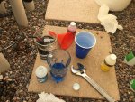
Enjoying this content?

Support TFP with a donation.

Give Support